
In this article, I will explore the development of a specialized calculation software designed to facilitate the rapid and accurate parameter estimation for off grid solar systems. As an engineer focused on renewable energy applications, I have observed that the design and implementation of off grid solar systems often require complex calculations to determine key components such as photovoltaic (PV) array power and battery storage capacity. The need for on-site, quick computations led me to create a software solution based on the Symbian S60V5 operating platform, which enables professionals to perform these calculations efficiently using mobile devices. The off grid solar system is a critical solution for remote areas without access to the public grid, and its design hinges on precise mathematical models to ensure reliability and cost-effectiveness.
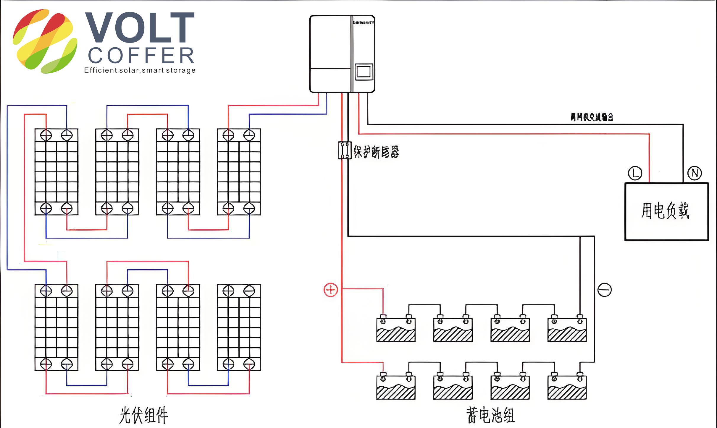
An off grid solar system typically consists of PV modules, a charge controller, batteries for energy storage, and optionally an inverter for AC loads. The system operates independently of the utility grid, making it ideal for applications in rural electrification, telecommunications, and emergency power supplies. The core challenge in designing such systems lies in balancing the energy generation from solar panels with the energy consumption of loads, while accounting for environmental factors like solar irradiation and weather conditions. Proper sizing of the PV array and battery bank is essential to avoid system failures during periods of low sunlight, such as prolonged cloudy days. This is where mathematical formulas come into play, allowing for the optimization of system parameters based on local data and load profiles.
To begin with, the power output of the PV array in an off grid solar system must be calculated to meet the daily energy demands of the connected loads. The formula for determining the total power of the PV array is derived from energy balance principles and incorporates various loss factors. It can be expressed as:
$$ P = \frac{17.2 \times K_{p1} \times P_l \times H_l}{K_{p2} \times K_{p3} \times H_p \times V} $$
In this equation, \( P \) represents the required PV array power in watts (W), \( P_l \) is the total power of the system loads in watts (W), \( H_l \) is the daily operating hours of the loads in hours (h), \( H_p \) is the local equivalent peak sun hours (h), and \( V \) is the DC system voltage in volts (V). The coefficients \( K_{p1} \), \( K_{p2} \), and \( K_{p3} \) account for system losses: \( K_{p1} \) is the comprehensive loss coefficient for PV modules, typically ranging from 1.05 to 1.15; \( K_{p2} \) is the battery charging efficiency, usually between 0.85 and 0.95; and \( K_{p3} \) is the wiring loss coefficient, often set between 0.95 and 0.98. These coefficients ensure that real-world inefficiencies are considered, making the off grid solar system design more robust. For instance, if the load power is 500 W, operating for 6 hours daily, with a peak sun hours of 4.5 h and a system voltage of 24 V, and using default loss coefficients, the PV power can be computed step by step to ensure accuracy.
Similarly, the battery capacity calculation is crucial for storing sufficient energy to power the loads during periods without sunlight. The formula for the battery capacity in ampere-hours (Ah) is given by:
$$ C = \frac{H_c \times P_l}{K_{b1} \times K_{b2} \times K_{b3} \times V} $$
Here, \( C \) denotes the battery capacity in Ah, \( H_c \) is the longest continuous no-sunshine period in hours (h), which represents the autonomy days, and \( P_l \), \( V \) are as defined earlier. The coefficients include \( K_{b1} \), the battery depth of discharge coefficient, typically 0.70 to 0.85; \( K_{b2} \), the inverter efficiency coefficient, ranging from 0.80 to 0.95 (set to 1.00 for DC systems); and \( K_{b3} \), the wiring loss coefficient, similar to the PV calculation. This equation ensures that the off grid solar system can sustain the load for the specified duration, such as three consecutive cloudy days, by selecting an appropriately sized battery bank. For example, with a load of 500 W, a 72-hour autonomy, and a 24 V system, the battery capacity can be determined to prevent under-sizing or over-sizing, which impacts both reliability and cost.
To illustrate the typical values and ranges for these parameters, I have compiled a table that summarizes the key variables involved in the design of an off grid solar system. This table serves as a quick reference for engineers and designers, highlighting the common defaults and allowable ranges for the coefficients used in the formulas.
| Parameter | Symbol | Typical Value Range | Description |
|---|---|---|---|
| Load Power | \( P_l \) | Varies (e.g., 100-5000 W) | Total power consumption of connected loads |
| Daily Operating Hours | \( H_l \) | Varies (e.g., 4-24 h) | Number of hours loads are used per day |
| Peak Sun Hours | \( H_p \) | Depends on location (e.g., 3-6 h) | Local solar irradiation equivalent to peak sun |
| System Voltage | \( V \) | 12, 24, 48 V, etc. | DC voltage of the off grid solar system |
| PV Loss Coefficient | \( K_{p1} \) | 1.05 – 1.15 | Accounts for losses in PV modules and soiling |
| Battery Charging Efficiency | \( K_{p2} \) | 0.85 – 0.95 | Efficiency of energy storage in batteries |
| Wiring Loss Coefficient | \( K_{p3} \) | 0.95 – 0.98 | Losses due to electrical resistance in cables |
| Autonomy Hours | \( H_c \) | Varies (e.g., 24-120 h) | Longest period without sunshine for battery backup |
| Battery Depth of Discharge | \( K_{b1} \) | 0.70 – 0.85 | Permissible discharge level to prolong battery life |
| Inverter Efficiency | \( K_{b2} \) | 0.80 – 0.95 (1.00 for DC) | Efficiency of converting DC to AC power |
Another important aspect of designing an off grid solar system is the configuration of the PV modules and batteries. Once the total PV power and battery capacity are calculated, the number of modules and batteries in series and parallel can be determined based on the system voltage and the specifications of individual components. For example, if a PV module has a rated voltage of 12 V and power of 100 W, and the system voltage is 24 V, then two modules would be connected in series to achieve the required voltage, and additional parallel strings would be added to meet the power demand. Similarly, for batteries, if each battery is 12 V and 100 Ah, and the system requires 24 V and 200 Ah, two batteries in series would provide the voltage, and two such strings in parallel would supply the capacity. This modular approach allows for flexibility in designing the off grid solar system to match specific site conditions.
The development of the calculation software for off grid solar systems was motivated by the need for a portable tool that could perform these computations on-the-go. I chose the Symbian S60V5 operating platform due to its widespread use in smartphones at the time, which offered touchscreen support and a robust environment for application development. The software was built using Carbide C++ as the integrated development environment (IDE), along with the S60V5 SDK, ActivePerl for scripting, and JRE for Java runtime support. These tools enabled the creation of a native application that could run efficiently on mobile devices, providing a user-friendly interface for inputting parameters and obtaining results quickly. The software’s workflow involves initializing the application, prompting the user to enter values such as load power, operating hours, autonomy days, and system voltage, with options to adjust the loss coefficients from their defaults. Upon calculation, it outputs the required PV array power and battery capacity, which can then be used to select standard components from manufacturer catalogs.
In terms of software functionality, the program incorporates error handling to ensure that inputs are within reasonable ranges, such as positive values for power and hours, and coefficients between their minimum and maximum limits. The use of default values for coefficients like \( K_{p1} = 1.05 \), \( K_{p2} = 0.85 \), \( K_{b1} = 0.70 \), \( K_{b3} = 0.97 \), and \( K_{b2} = 1.00 \) (for DC systems) allows for rapid calculations, while still permitting customization based on specific project requirements. For instance, in a scenario with a DC off grid solar system where the load is 30 W, operating for 10 hours daily, with an autonomy of 3 days (72 hours), and a system voltage of 12 V, the software computes the PV power as approximately 136.90 W and the battery capacity as 110.45 Ah. Based on standard component sizes, this might translate to selecting a 140 W PV module and a 12 V 120 Ah battery, ensuring the system meets the energy needs reliably.
The integration of such a software tool into the design process of an off grid solar system offers significant advantages, including reduced calculation time, minimized human error, and enhanced accessibility for field engineers. By leveraging mobile technology, professionals can perform iterations and sensitivity analyses on-site, adjusting parameters like autonomy days or loss coefficients to see how they affect the system sizing. This is particularly useful for off grid solar systems in variable environments, where local solar data might change seasonally. Moreover, the software’s output can be directly used to generate preliminary design reports, facilitating communication with stakeholders and accelerating project deployment. The emphasis on the term off grid solar system throughout this process underscores its importance in renewable energy solutions, especially in regions where grid extension is economically unfeasible.
To further elaborate on the mathematical foundations, the formulas for PV power and battery capacity can be extended to include additional factors, such as temperature corrections for PV performance or aging factors for batteries. For example, the actual power output of a PV module can be affected by temperature, which might be incorporated using a coefficient like \( K_t \), leading to a modified formula:
$$ P = \frac{17.2 \times K_{p1} \times P_l \times H_l}{K_{p2} \times K_{p3} \times H_p \times V} \times K_t $$
where \( K_t \) represents the temperature derating factor, typically around 0.85 to 0.90 for silicon-based modules. Similarly, for battery capacity, a cycle life factor might be included to account for degradation over time, ensuring the off grid solar system remains reliable throughout its lifespan. These refinements highlight the complexity involved in designing a robust off grid solar system and the value of software tools that can handle such nuances.
In conclusion, the development of this calculation software for off grid solar systems represents a practical approach to addressing the challenges in renewable energy system design. By combining mathematical models with mobile technology, it provides an efficient solution for sizing PV arrays and batteries, ultimately contributing to the wider adoption of off grid solar systems. Future enhancements could include integration with GPS for location-specific solar data, cloud-based storage for project history, and support for additional renewable sources like wind or hydro. As the demand for sustainable energy grows, tools like this will play a crucial role in making off grid solar systems more accessible and reliable for communities worldwide. The repeated focus on the off grid solar system in this discussion aims to reinforce its significance in the global energy transition, emphasizing the need for innovative solutions that bridge the gap between technology and practical application.