
The depletion of traditional energy resources, coupled with stringent environmental regulations, has catalyzed a significant transformation in the power sector. Central to this shift is the surging demand for energy storage, with battery energy storage system technology standing at the forefront. Compared to conventional energy balancing methods, a modern battery energy storage system excels in load shifting (peak shaving and valley filling), stabilizing electrical grids, and providing efficient, reliable power supply. To fully harness these advantages, meticulous design of the battery system is paramount. This involves integrating sophisticated hardware and software, partitioning functional modules, and prioritizing electrical safety and utilization efficiency. As technology evolves, continuous innovation is essential to optimize the design and development of future battery energy storage system platforms.
1. Overview of Lithium-Ion Battery Energy Storage Products
Energy storage technologies are broadly categorized into mechanical, electromagnetic, and electrochemical storage. Mechanical storage often suffers from geographical and environmental constraints, while electromagnetic storage lags in commercial maturity. Electrochemical storage, particularly using lithium-ion batteries, exhibits tremendous potential due to its high energy density, high power capability, long cycle life, and rapid response characteristics. These attributes make lithium-ion-based battery energy storage system units ideal for applications requiring power quality regulation and uninterrupted supply. To ensure reliable operation across diverse scenarios, a comprehensive battery energy storage system must be scientifically designed, incorporating specialized equipment and a robust management framework.
2. Key Design Considerations for a Battery Energy Storage System
2.1 System Architecture
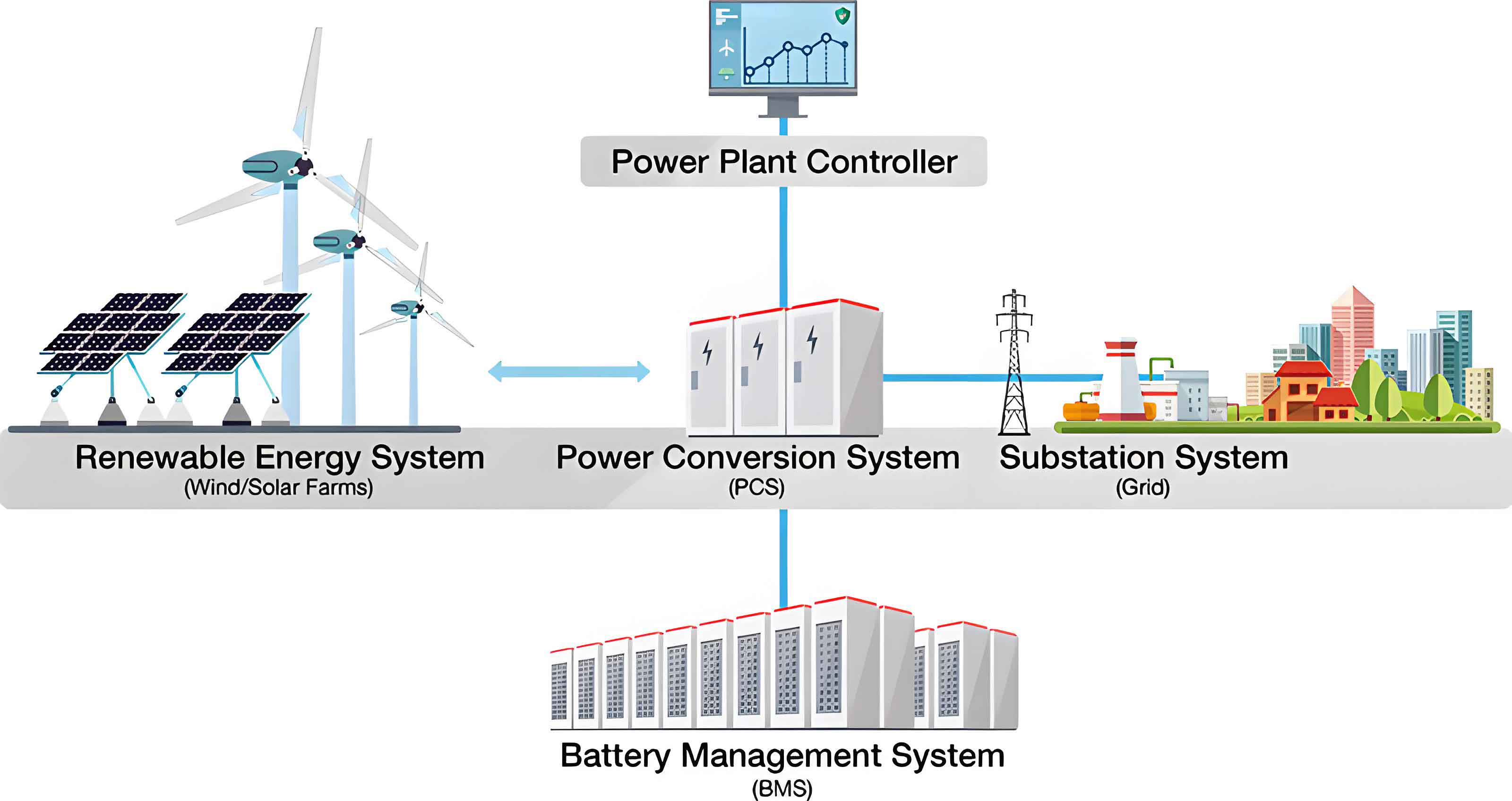
The foundation of a safe and reliable battery energy storage system lies in its architecture. A common approach involves series-connecting multiple battery cells to form a high-voltage string. For instance, a module may consist of 12 series-connected 280Ah Lithium Iron Phosphate (LFP) cells. The management of such a system is typically hierarchical, featuring a top-level Master Battery Management System (BMS) and subordinate slave BMS units.
The Master BMS is responsible for system-wide data aggregation, state monitoring, and communication with external controllers. It continuously collects parameters like total pack voltage, current, and temperature, processes this data, and presents it via a Human-Machine Interface (HMI) for performance evaluation and control. An effective architecture for the Master BMS is the PC/104 industrial computer form factor. This stackable, modular, and compact bus offers low power consumption and integrates common peripherals like AD converters, CAN, and Ethernet interfaces, simplifying overall system design. Its computational power is well-suited for handling the substantial data flows within a battery energy storage system.
The slave BMS, often centered on a dedicated microcontroller like the Freescale MC9S12XS128, performs critical real-time tasks at the cell or module level. It precisely measures individual cell voltages, temperatures, and module current. This data is used for local State of Charge (SOC) estimation and cell balancing before being transmitted to the Master BMS via a CAN bus for consolidated action.
Key parameters for a typical LFP cell used in such a system are summarized below:
| Parameter | Specification |
|---|---|
| Nominal Capacity | 280 Ah |
| Nominal Voltage | 3.2 V |
| Operating Voltage Range | 2.8 V to 3.65 V |
| Chemistry | LFP (LiFePO₄) |
| Standard Charge/Discharge Rate | 0.5C |
| Cycle Life (to 70% capacity) | >6000 cycles @ 0.5C |
2.2 Hardware Circuit Design
The hardware design is the nervous system of the battery energy storage system, responsible for accurate data acquisition and safe control.
2.2.1 Voltage Acquisition
For LFP batteries, the open-circuit voltage (OCV) is a primary indicator of State of Charge (SOC) and health. Precise, synchronous measurement of all series-connected cell voltages is crucial for detecting overcharge or over-discharge conditions. Dedicated battery monitoring Integrated Circuits (ICs) like the LTC6802-2 are employed for this task. A single LTC6802-2 can measure up to 12 series-connected cells with high accuracy (typically within a few millivolts) in approximately 13ms. Its multi-wire, high-voltage input capability and daisy-chainable architecture via a 4-bit address make it scalable for large battery energy storage system packs with hundreds of cells.
The measurement principle involves a precision analog-to-digital converter (ADC). The voltage \( V_{cell} \) of a cell is measured relative to the stack. The accuracy is paramount for reliable SOC calculation. The error budget must account for IC gain error, offset error, and noise. A simplified error model for a measured cell voltage can be expressed as:
$$ V_{measured,i} = V_{true,i} \cdot (1 + G_{err}) + V_{offset} + V_{noise} $$
Where \( V_{true,i} \) is the actual cell voltage, \( G_{err} \) is the gain error, \( V_{offset} \) is the offset error, and \( V_{noise} \) is the random measurement noise. High-precision components and calibration routines are used to minimize \( G_{err} \) and \( V_{offset} \).
| Performance Metric | Typical Value (LTC6802-2) |
|---|---|
| Total Measurement Error | < ±1.2mV |
| Input Voltage Range per Channel | 0V to 5V |
| Maximum Stack Voltage | >60V |
| Communication Interface | SPI |
2.2.2 Current Acquisition
Current measurement is vital for calculating charge throughput (Ah), real-time power, and for advanced SOC estimation using Coulomb counting. In a series string, the current is uniform, so typically one high-precision sensor monitors the main pack current. Requirements include high sampling frequency for fast protection and wide dynamic range.
Two common technologies are used:
- Shunt Resistors: Measure voltage drop across a known, low-value precision resistor. Power loss is given by \( P_{loss} = I^2 \cdot R_{shunt} \).
- Hall-Effect Sensors: Isolated sensors that measure the magnetic field generated by the current-carrying conductor. They offer galvanic isolation and very low power loss but can be susceptible to DC drift and external magnetic fields.
The choice involves a trade-off between cost, accuracy, and loss. For a high-current battery energy storage system, a closed-loop Hall-effect sensor is often preferred for its isolation and low loss. The output voltage \( V_{out} \) of a linear Hall sensor is related to the primary current \( I_p \) by its sensitivity \( S \):
$$ V_{out} = V_{ref} + S \cdot I_p $$
Where \( V_{ref} \) is the zero-current output voltage (e.g., 2.5V for a bidirectional sensor).
| Sensor Type | Advantages | Disadvantages |
|---|---|---|
| Shunt Resistor | Excellent accuracy, low cost, wide bandwidth | Non-isolated, significant I²R power loss |
| Open-Loop Hall | Isolated, low loss, compact | Lower accuracy, temperature drift, sensitive to stray fields |
| Closed-Loop Hall | Isolated, high accuracy, excellent linearity, low drift | Higher cost, larger size, consumes more power |
2.2.3 Temperature Acquisition
Temperature profoundly impacts battery performance, safety, and lifespan. It affects internal resistance, charge acceptance, and degradation rate. Excessive temperature accelerates aging and can lead to thermal runaway, while low temperature reduces power capability and can cause lithium plating. Therefore, a comprehensive battery energy storage system monitors temperature at multiple points: cell surfaces, busbars, and ambient environment.
The DS18B20 digital temperature sensor is a popular choice due to its single-wire bus interface, allowing multiple sensors to be connected on one microcontroller pin, and its sufficient accuracy for battery monitoring (-55°C to +125°C range). Upon detecting high temperatures, the BMS can activate cooling systems; for low temperatures, it can inhibit charging or enable heating.
The relationship between temperature and a battery’s internal resistance \( R_{int} \) is often modeled empirically, such as with the Arrhenius equation or a polynomial fit:
$$ R_{int}(T) \approx R_{int}(T_{ref}) \cdot \exp \left[ \frac{E_a}{R} \left( \frac{1}{T} – \frac{1}{T_{ref}} \right) \right] $$
Where \( E_a \) is the activation energy, \( R \) is the gas constant, and \( T \) is the absolute temperature. Monitoring \( T \) allows the BMS to dynamically adjust power limits for safety and longevity.
| Monitoring Point | Purpose | Typical Thresholds (LFP Example) |
|---|---|---|
| Cell Surface (per module) | Prevent overheating, manage cell degradation | Warning: >45°C; Fault: >55°C |
| Busbar/Connection | Detect loose connections or high resistance | Warning: ΔT > 15°C above ambient |
| Ambient (inside enclosure) | Control HVAC system, ensure operating envelope | Cooling ON: >30°C; Heating ON: <5°C |
2.2.4 CAN Communication Network
The Controller Area Network (CAN) bus is the industrial-standard backbone for communication within a battery energy storage system. Its robustness, multi-master capability, and error-checking mechanisms make it ideal for the harsh electromagnetic environment of power electronics. The communication follows standardized protocols, such as the Chinese industry standard JB/T 11138-2011 or the more international ISO 15118 and SAE J1939 derivatives for energy storage.
The design involves a CAN controller (often integrated into the microcontroller) and a CAN transceiver (e.g., TJA1050) for physical layer signaling. The software initializes the baud rate, acceptance filters, and interrupt handlers. Data like cell voltages, temperatures, and status are packaged into standardized CAN frames with unique identifiers (IDs) and Cyclic Redundancy Check (CRC) bytes for integrity.
The bit timing for the CAN bus is critical for reliable communication. The nominal bit time \( t_{bit} \) is divided into segments:
$$ t_{bit} = t_{SyncSeg} + t_{PropSeg} + t_{PhaseSeg1} + t_{PhaseSeg2} $$
Where \( t_{SyncSeg} \) is fixed at 1 Time Quantum (TQ). \( t_{PropSeg} \) compensates for physical delay, and \( t_{PhaseSeg1} \) & \( t_{PhaseSeg2} \) provide sampling point adjustment. For a 500 kbps bus with a microcontroller clock of 16 MHz and a prescaler, the parameters must be carefully calculated to meet the CAN specification’s requirements for re-synchronization.
2.3 Software Design
The software orchestrates all hardware functions and implements the core intelligence of the battery energy storage system. It is typically developed in a layered fashion.
Firmware (Slave BMS): Developed in C using an IDE like CodeWarrior for the MCU. Key modules include:
- Initialization: Configures clocks, GPIOs, ADCs, timers, CAN, and SPI/I2C peripherals.
- Data Acquisition Scheduler: A time-triggered loop that reads voltages (via SPI from LTC6802), currents (via ADC), and temperatures (via 1-Wire).
- State Estimation: Implements algorithms for State of Charge (SOC) and State of Health (SOH). A common hybrid method combines Coulomb counting with voltage/temperature correction:
$$ SOC(t) = SOC(t_0) + \frac{1}{Q_{nom}} \int_{t_0}^{t} \eta(I, T) \cdot I(\tau) \, d\tau $$
Where \( Q_{nom} \) is the nominal capacity and \( \eta \) is the coulombic efficiency, often a function of current \( I \) and temperature \( T \). This is periodically corrected by an OCV-SOC lookup table when the battery is at rest. - Balancing Control: Activates passive (resistive) or active (capacitive/inductive) balancing circuits to equalize cell SOCs.
- Fault Diagnosis & Protection: Continuously checks for over-voltage, under-voltage, over-current, over-temperature, and internal communication faults. Triggers safety actions (e.g., open contactors).
- Communication Handler: Manages reception and transmission of CAN messages with the Master BMS.
Master BMS & HMI Software: Often runs on a Linux or RTOS platform on the PC/104 module. It aggregates data from all slave units, performs system-level SOC/SOH calculation, logs historical data, and communicates with the wider energy management system (EMS). The HMI, developed using frameworks like Qt or embedded web servers, provides visualization of real-time data, alarms, and system configuration interfaces.
2.4 Other Critical Design Aspects
Beyond the BMS, the complete battery energy storage system design encompasses several other crucial areas:
Cell Selection & Qualification: Rigorous testing of battery cells per standards like GB/T 36276 or UL 1973 is essential. Key parameters include energy density, cycle life under specific depth-of-discharge (DOD) conditions, rate capability, and safety performance under abuse (nail penetration, overcharge, short circuit).
Mechanical & Thermal System Design: The enclosure must provide structural support, environmental protection (IP rating), and thermal management. Air cooling (fans, ducts) is common, but liquid cooling is increasingly used for high-density battery energy storage system packs for superior temperature uniformity, governed by heat transfer equations:
$$ \dot{Q}_{gen} = \dot{m} \cdot c_p \cdot \Delta T $$
Where \( \dot{Q}_{gen} \) is the heat generated by the battery pack (from irreversible losses \( I^2R \) and reversible entropic heat), \( \dot{m} \) is the coolant mass flow rate, \( c_p \) is its specific heat capacity, and \( \Delta T \) is its temperature rise across the pack.
Electrical Safety & Protection: This includes properly rated contactors for main circuit connection/disconnection, pre-charge circuits to limit inrush current into capacitive inverters, and comprehensive fusing at the pack and module level. Isolation monitoring devices continuously check the resistance between the high-voltage DC bus and the chassis ground to prevent electric shock hazards.
Grid Integration Power Conversion System (PCS): The bidirectional inverter/charger is the interface between the DC battery and the AC grid. Its control strategy, following grid codes for frequency, voltage, and power factor, determines how the battery energy storage system provides services like frequency regulation or solar smoothing.
3. Future Trends and Conclusion
The design and development of a battery energy storage system is a multidisciplinary challenge integrating electrochemistry, power electronics, control theory, and software engineering. The current trajectory points toward several key trends:
Advanced Battery Chemistries: While LFP dominates for stationary storage due to safety and longevity, sodium-ion and solid-state batteries promise lower cost and higher energy density for future battery energy storage system deployments.
AI-Driven BMS: Machine learning algorithms will enhance state estimation (SOC, SOH, State of Power), predict remaining useful life (RUL) with higher accuracy, and optimize charging strategies in real-time based on usage patterns and cell degradation models.
System-Level Digital Twins: Creating a virtual replica of the physical battery energy storage system will enable proactive maintenance, performance simulation, and safe operational boundary exploration without risking the actual asset.
Standardization & Modularity: The industry is moving towards standardized, plug-and-play battery modules and communication protocols to reduce engineering costs, simplify deployment, and facilitate recycling.
In conclusion, a well-designed battery energy storage system is a cornerstone of the modern renewable energy landscape. Its development requires a holistic approach, balancing performance, safety, reliability, and cost. By leveraging advanced hardware, sophisticated software algorithms, and rigorous system integration practices, engineers can create storage solutions that are not only technically proficient but also economically viable, thereby accelerating the global transition to a sustainable energy future.