
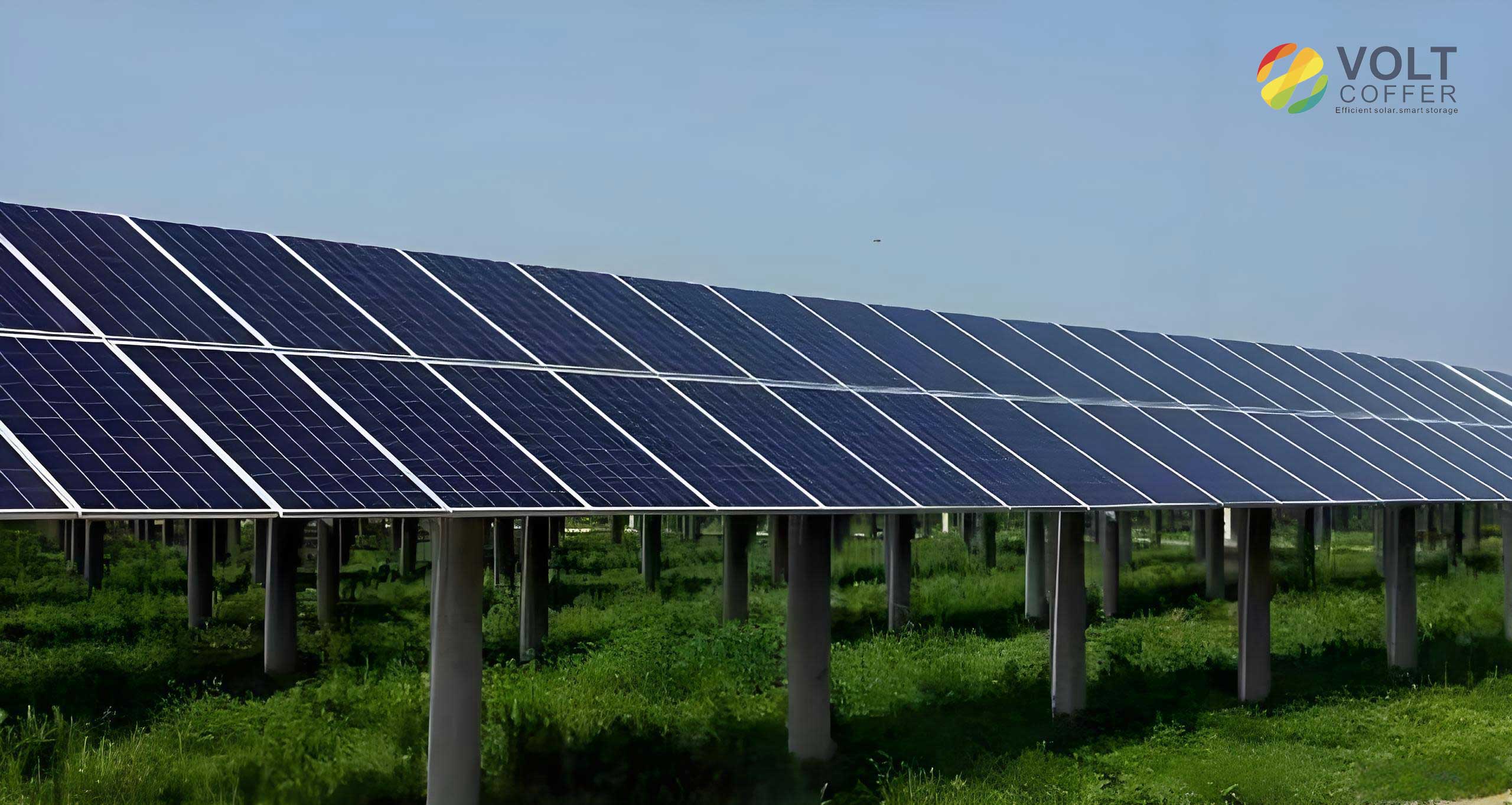
I present the design of a low‑cost autonomous cleaning robot specifically tailored for photovoltaic panels. Solar panels are among the earliest deployed renewable energy technologies, offering mature supply chains, wide adaptability, and relatively low cost. However, the accumulation of dust, sand, and other particulate matter on the surface of solar panels can severely degrade their power generation efficiency. Studies have shown that after six months without cleaning, the power loss caused by dust coverage can average 15.27% or more. For desert‑based solar farms, the reduction in efficiency can be as high as 80%. Traditional manual cleaning with brooms and cloths is inefficient, expensive, and may even damage the panels. Various automated solutions have been proposed, including semi‑automatic rotary brushes, track‑mounted robots, rail‑guided systems, and vacuum‑adhesion robots. Many of these either require expensive sensors, complicated infrastructure, or are not well‑suited for dense or irregularly spaced solar panel arrays.
My approach focuses on a compact tracked chassis equipped with a rotating cleaning brush, driven by a low‑cost 32‑bit microcontroller (STM32F103C8T6). The system uses a dual‑loop PID control strategy for yaw and velocity, enabling stable straight‑line motion despite track slippage. A Hall‑encoder‑equipped DC motor drives the cleaning brush, and its PWM duty cycle is monitored in real time to detect the edge of solar panels without additional sensors. Infrared sensors on the tail and sides provide backup fall‑prevention. A dedicated path‑planning algorithm enables the robot to autonomously sweep the entire surface of solar panels in a back‑and‑forth manner. Experiments conducted on a 100 cm × 60 cm tempered glass plate (simulating solar panels) covered with fine sand demonstrate the feasibility and effectiveness of the proposed design.
1. System Architecture and Mechanical Design
The prototype measures 27.5 cm in length, 27 cm in width, and 12.5 cm in height, with a total mass of 4 kg. It uses a tracked chassis driven by two high‑torque DC gear‑motors (reduction ratio 1:30, rated torque 0.25 N·m). Each motor has a Hall encoder with 13 lines per revolution, and the microcontroller captures quadrature pulses at 4× frequency for precise speed feedback. The tracks are made of hard plastic with silicone strips attached to each link to increase friction on the glass surface of solar panels. A 12 V, 2550 mAh lithium battery powers the robot.
The cleaning brush assembly is a custom industrial roller brush with nylon bristles of medium hardness. The bristle length is 20 mm, and the effective cleaning width is 170 mm. Two 3D‑printed resin support arms hold the brush at the front of the chassis. A dedicated DC gear‑motor (reduction ratio 1:34, rated torque 0.15 N·m) drives the brush via a synchronous belt. The brush center is 55 mm above the ground, ensuring a bristle compression of 3‑5 mm against the surface of solar panels.
Fall prevention is achieved by two mechanisms. First, the front edge detection relies on the PWM duty cycle of the brush motor: when the brush leaves the panel surface, the load drops sharply, and the duty cycle falls below a voltage‑dependent threshold. Second, four infrared sensors (detection range up to 9 cm) are mounted on the left, right, and rear sides. The tail sensors are oriented vertically downward, while the side sensors are tilted to detect the panel edge.
2. Control System Design
2.1 Hardware Components
The main controller is an STM32F103C8T6 running at 72 MHz. It has four timer modules: TIM1 generates three PWM signals (20 kHz) for the two track motors and the brush motor; the other three timers are used for encoder pulse capture (hardware filter set to 10, 4× quadrature). An MPU6050 IMU provides yaw angle via I²C, and the DMP library suppresses drift. Four infrared sensors are connected to GPIO pins. An OLED display and an HC‑05 Bluetooth module communicate with the user. Power management includes a DC‑DC converter (RT8289, 5 V/5 A) and an LDO (RT9013, 3.3 V). Battery voltage is monitored via an ADC pin.
2.2 Control Algorithm
I adopt an incremental PID controller for the motor speed and yaw correction. The incremental PID formula is:
$$ \Delta U(t) = K_p [e(t)-e(t-1)] + K_i e(t) + K_d [e(t)-2e(t-1)+e(t-2)] $$
where $e(t)$ is the error at time $t$. The final output $U(t)$ is the sum of all previous $\Delta U$ increments.
To maintain a straight trajectory on solar panels despite track slippage and uneven weight distribution, I use a cascaded yaw‑velocity PID structure (dual‑loop). The outer loop adjusts the yaw error using the IMU, and its output modifies the target speeds of the left and right track motors. The inner loops regulate the motor speeds individually. The execution frequency is 50 Hz. The relationship between the number of encoder pulses $N$ per control cycle (20 ms) and the motor speed $R_p$ (in r/min) is:
$$ N = \frac{R_p \times P_r \times 4 \times R_d \times T}{1000 \times 6} $$
where $P_r$ = 13 lines/rev (quadrature gives 52 pulses/rev), $R_d$ = 30 (track motor) or 34 (brush motor), and $T$ = 20 ms.
The yaw angle from the IMU ranges from ‑180° to +180°. The error $Err\_Yaw$ is computed with minimum‑turn logic:
$$ Err\_Yaw = Cur\_Yaw – Tar\_Yaw, \; Cur\_Yaw, Tar\_Yaw \in [-180^\circ, +180^\circ] $$
$$ \text{if } Err\_Yaw > 180^\circ,\; Err\_Yaw = Err\_Yaw – 360^\circ $$
$$ \text{if } Err\_Yaw < -180^\circ,\; Err\_Yaw = Err\_Yaw + 360^\circ $$
The brush motor is also controlled by a speed PID loop (50 Hz) to maintain a constant rotation speed (target ‑154 r/min) regardless of load variations.
2.3 Edge Detection via Brush Duty Cycle
When the cleaning brush runs on the surface of solar panels, the load resistance causes the PID controller to output a higher PWM duty cycle. When the robot reaches the edge of a panel, the brush becomes airborne, the load drops abruptly, and the duty cycle decreases significantly. I exploit this phenomenon for front‑edge detection. However, the duty cycle depends on the battery voltage. Therefore, I performed a series of experiments at different battery voltages (12.2 V down to 9.2 V) with a panel inclination of 10° and no dust. For each voltage, I recorded the duty cycle mean and standard deviation for both loaded (on the panel) and unloaded (at the edge) conditions. The probability density of the duty cycle shows two distinct peaks. Using a Six‑Sigma approach, I set a threshold at +6σ above the unloaded peak. The thresholds at different voltages were fitted with a cubic polynomial:
$$ y = -3x^3 + 143.31x^2 – 2175.89x + 12455.16 $$
where $x$ is the battery voltage (in volts) and $y$ is the duty cycle threshold. If the measured duty cycle falls below this threshold, the robot immediately brakes to prevent falling off solar panels.
To validate, I conducted over 50 experiments on a 100 cm × 60 cm glass plate without dust, with battery voltage varying between 11.4 V and 9.6 V. In all cases, the robot stopped before the brush fully left the panel.
2.4 Autonomous Cleaning Path Planning
Given the limited sensing hardware, I devised a simple yet effective path‑planning algorithm for solar panels. The robot starts at the bottom‑left corner of the panel (after initial IMU stabilization). In the automatic mode, it performs the following sequence:
- Record the current yaw as the desired direction and start the brush rotating forward (same direction as forward movement). Move forward while using the yaw PID to keep a straight line.
- If the left‑side infrared sensor detects the edge of solar panels, the robot temporarily steers slightly right until the sensor no longer detects the edge, then resumes the original direction. This corrects lateral drift.
- When the front edge is detected (brush duty cycle below threshold), the robot stops, reverses direction (backward), and rotates the brush backward to help disengage from the edge. The brush then rotates forward again as the robot moves backward.
- When the tail infrared sensors detect the bottom edge, the robot stops. If one of the two tail sensors triggers earlier than the other (indicating skew), the robot rotates (left or right) until both sensors detect the panel again, thus realigning.
- The robot then moves forward a short distance until the tail sensors no longer detect the edge.
- The robot rotates 45° clockwise (using yaw control) and moves forward for a predetermined time $T_s$ to shift to the next cleaning lane. The shift distance $L$ is given by:
$$ L = \frac{R_p \times T_s \times 2\pi r}{60} $$
where $R_p$ = 24 r/min, $r$ = 2 cm, and $T_s$ ≈ 3.4 s, yielding $L$ ≈ 17 cm. Since the brush cleaning width is 170 mm, and $L$ is smaller than 170 mm, overlapping coverage ensures no gaps.
- After the shift, the robot rotates 45° counter‑clockwise back to the original yaw and starts a new forward/backward cleaning pass.
- The process repeats until one of two termination conditions is met: (a) during a lane shift, the brush duty cycle indicates the right edge of solar panels; (b) during a forward cleaning pass, the right‑side infrared sensor detects the panel edge. In either case, the robot performs a final backward movement to the bottom edge and stops.
This algorithm effectively covers the entire surface of solar panels without needing external reference points or expensive sensors.
3. Experimental Validation
3.1 PID Parameter Tuning
I tuned the PID parameters through trial‑and‑error based on step‑response data. The final values are:
| Controller | Kp | Ki | Kd | Output Limit |
|---|---|---|---|---|
| Track motor speed (left & right) | 25 | 12 | 16 | 3550 (duty cycle) |
| Yaw outer loop (left motor) | 0.8 | 0.006 | 0.1 | ±40 (differential speed) |
| Yaw outer loop (right motor) | 1.0 | 0.005 | 0.1 | ±40 (differential speed) |
| Brush motor speed | 16 | 5 | 2.5 | 3550 (duty cycle) |
3.2 Yaw‑Velocity Control Performance
I recorded the yaw angle and motor speeds during forward and backward cleaning runs on a clean glass plate (no dust). The desired yaw was set to -8.8°. The plots (not shown, but data collected) show that despite track slip and brush friction, the yaw error remained within ±2° most of the time. Backward motion introduced additional disturbance because the brush rotates opposite to the movement direction; however, the controller still maintained acceptable tracking.
3.3 Brush Duty Cycle Analysis under Various Conditions
I tested the brush motor duty cycle under different panel inclinations (0°, 10°, 20°) and battery voltages (12.2 V, 11.4 V, 10.4 V, 9.2 V) with no dust. The mean and standard deviation of the duty cycle for loaded (on panel) and unloaded (at edge) states were recorded. Results show that inclination has a negligible effect, while voltage strongly influences the duty cycle. The loaded duty cycle is always significantly higher than the unloaded one. For example, at 10.4 V, the loaded mean was about 2150, and the unloaded mean was about 1850.
I also varied the sand dust density from 0 to 60 g/m² on a plate at 10° inclination and 12.3 V battery. The loaded duty cycle increased with dust density, while the unloaded value remained nearly constant (around 1850). This confirms that the edge detection threshold method is robust to dust accumulation.
3.4 Edge Detection Verification
I implemented the fitted cubic threshold curve in the microcontroller. In a representative test at 10.4 V, the brush duty cycle dropped from about 2150 to 1850 in less than 0.5 s when the robot reached the edge. The algorithm triggered braking, and the track motors stopped immediately. Over 50 runs, no fall event occurred.
3.5 Full Automatic Cleaning Experiments
I performed 50 automatic cleaning cycles on a 100 cm × 60 cm glass plate (10° inclination) covered with 60 g/m² fine sand. Each cycle consisted of several back‑and‑forth passes as described in the path‑planning algorithm. The battery voltage started around 11.4 V and dropped to about 9.6 V after 50 cycles. The average time per cleaning cycle was 163.02 s, and the average voltage drop per cycle was 0.0338 V. The cleaning coverage (percentage of the panel area actually swept) averaged 74.6%, leaving a small dead zone at the bottom edge. The dead zone width is constant; therefore, for larger solar panels, the coverage ratio increases. The cleaning efficiency (area per time) was 27.46 cm²/s, and with a full battery (12.6 V to 9 V), the robot can complete about 106.5 cycles, covering a total area of approximately 47.67 m².
Qualitatively, the cleaning effect was evaluated visually. After two consecutive automatic cycles, all visible sand was removed from the top and middle of the plate, with only a thin strip of sand remaining at the bottom edge. This residual can be removed manually or by adding a water spray mechanism in future designs.
3.6 Comparison with Existing Tracked Solutions
I compared my design with two other tracked cleaning robots reported in the literature: one using visual‑photoelectric sensors and one using a smart cleaning approach. The comparison table summarizes the hardware requirements:
| Feature | Visual‑Photoelectric Robot | Smart Cleaning Robot | My Proposed Robot |
|---|---|---|---|
| Vision sensor | Required (camera) | Not required | Not required |
| IMU | Unknown | Required | Low‑cost MPU6050 |
| Optical sensor | Required | Required | Low‑cost IR transceiver |
| Processor | High‑performance ARM | Ordinary MCU | Low‑cost MCU (STM32F103) |
| Vacuum chamber | Required | Not required | Not required |
| Water pump/ nozzle | Required | Required | Not required |
| Overall size | Large | Large | Small |
My design eliminates the need for expensive cameras, vacuum chambers, and water pumps, while still providing automatic edge detection and full‑panel coverage. The total bill‑of‑materials is significantly lower, making it suitable for large‑scale deployment.
4. Conclusion
I have designed and tested a low‑cost, tracked robot for cleaning solar panels. The robot uses a cascaded yaw‑velocity PID controller to maintain straight motion on sloped and dusty surfaces. Edge detection is achieved by monitoring the PWM duty cycle of the brush motor, which drops abruptly when the brush leaves the panel. A simple path‑planning algorithm allows the robot to autonomously sweep the entire surface of solar panels in a back‑and‑forth pattern, using infrared sensors for side and rear fall prevention and brush‑based detection for the front edge. Experiments on a 100 cm × 60 cm glass plate covered with sand demonstrate that the robot can effectively clean the panel, with an average coverage of 74.6% per cycle and a cleaning efficiency of 27.46 cm²/s. The robot can operate for about 106 cycles on a single battery charge, covering nearly 48 m². Comparison with existing tracked robots shows that my design achieves a similar level of autonomy with significantly lower hardware cost. Future improvements may include adding a water spray system, optimizing the cleaning path for larger solar panels, and implementing adaptive control to handle varying panel inclinations and surface conditions.