
In recent years, as an engineer specializing in renewable energy projects, I have observed a growing global focus on energy issues. Solar energy, being the most abundant resource on Earth, has gained significant attention for its applications and widespread adoption. The solar system, particularly photovoltaic technology, is increasingly integrated into various domains, reflecting its versatility and sustainability. Based on the characteristics of solar energy and practical needs, solar power generation is divided into solar thermal and photovoltaic systems, with the latter commonly referred to as solar photovoltaic power generation. This solar system is often hailed as an ideal power generation method, as it directly converts sunlight into electricity through solar panels without intermediate steps, producing no pollution during operation. Hence, it is recognized as a clean and new energy source, with its societal applications gradually expanding.
In my professional work, I have been involved in designing solar photovoltaic carports, which combine solar panels with building structures. This integration not only provides parking functionality but also incorporates power generation, insulation, rain protection, and shading by installing solar panels on the roof. The solar photovoltaic carport represents a promising future direction, with vast development prospects. In this article, I will delve into the structural design of such a solar system, emphasizing the foundation and support system, and highlighting how it embodies building-integrated photovoltaics (BIPV) by merging multiple functions into a practical and aesthetically pleasing solution.
From my perspective, the solar system in a carport setting begins with a thorough project overview. The site for this project is located in a coastal region of Zhejiang Province, China, characterized by specific design conditions. The basic design wind pressure is 0.9 kN/m², and the basic design snow pressure is 0.5 kN/m², with ground roughness classified as Category B. The seismic fortification intensity is set at 6 degrees. These parameters are crucial for ensuring the structural integrity of the solar system under environmental loads. To summarize key design inputs, I present the following table:
| Parameter | Value | Unit |
|---|---|---|
| Design Wind Pressure | 0.9 | kN/m² |
| Design Snow Pressure | 0.5 | kN/m² |
| Ground Roughness | B | Category |
| Seismic Intensity | 6 | Degree |
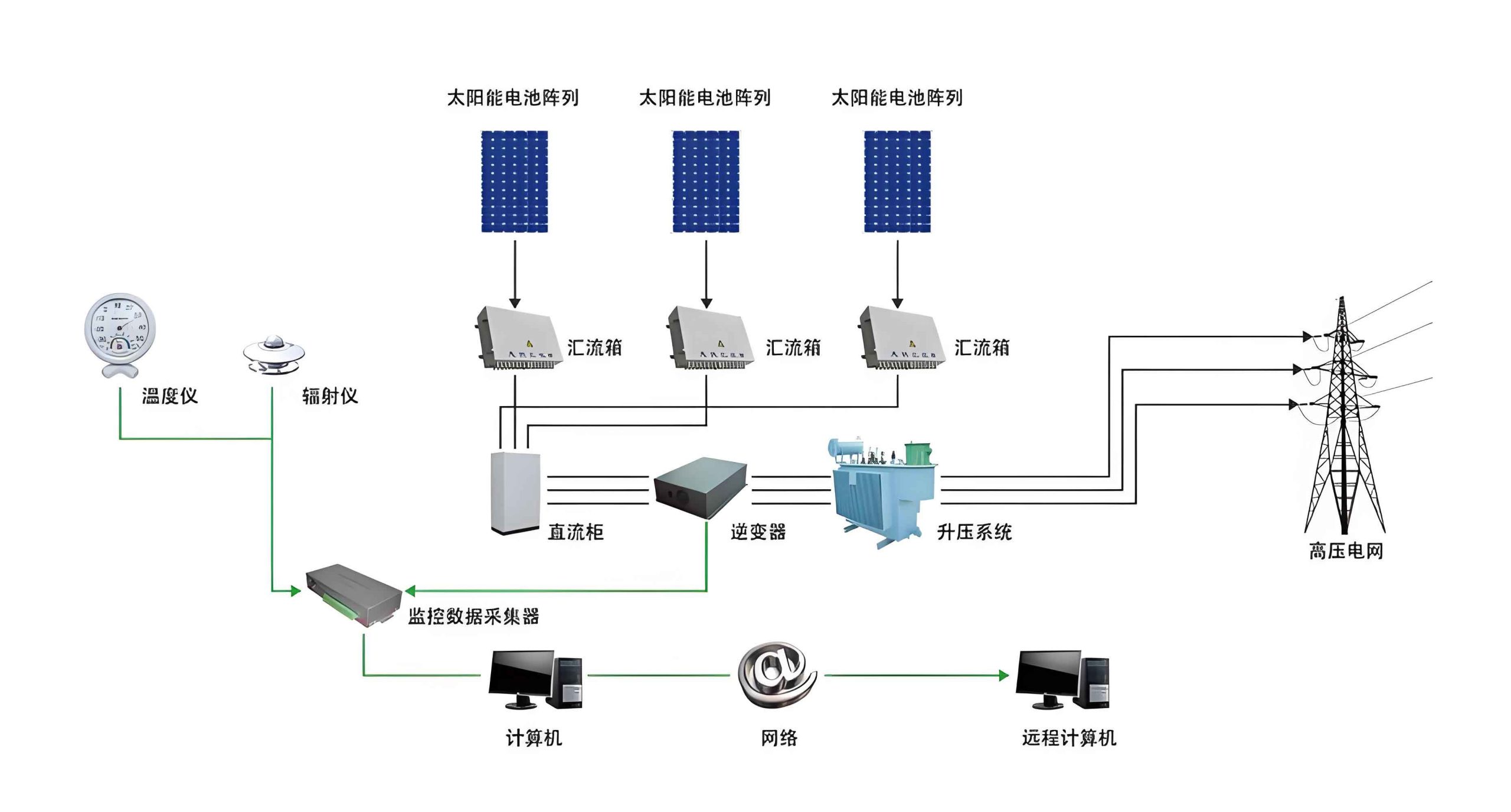
The solar system for the carport primarily consists of several components: the photovoltaic support structure, the solar panel array, the inverter and step-up system, and the lightning protection and grounding system. Each element plays a vital role in the overall functionality of the solar system. The photovoltaic support structure directly bears the solar panels and must withstand wind and snow loads. Based on local conditions, I design the support to meet these demands, optimizing the installation angle for maximum efficiency. The solar panel array is the core component that collects sunlight and converts it into electricity. Multiple panels are connected in series and parallel to form an array, with the total power output depending on factors like irradiance and panel efficiency. The inverter and step-up system includes intelligent combiner boxes, DC distribution cabinets, grid-tied inverters, and step-up transformers, ultimately integrating the solar system into the grid. The lightning protection and grounding system, comprising surge protectors, down conductors, and grounding grids, safeguards the solar system from lightning strikes and ensures operational safety.
To quantify the performance of the solar system, I often use formulas to estimate power generation. For instance, the theoretical power output of a solar panel array can be expressed as:
$$ P = \eta \cdot A \cdot G $$
where \( P \) is the power output in watts, \( \eta \) is the overall efficiency of the solar system (including panel and inverter efficiencies), \( A \) is the total area of the solar panels in square meters, and \( G \) is the solar irradiance in watts per square meter. In practice, I adjust for factors like temperature and shading. For example, if the solar system has an efficiency of 15%, an area of 100 m², and an average irradiance of 1000 W/m², the power output would be:
$$ P = 0.15 \times 100 \times 1000 = 15,000 \text{ W} = 15 \text{ kW} $$
This calculation helps in sizing the solar system for the carport application.
Now, focusing on the structural aspects, the foundation of the solar system is critical for stability. In this project, we used reinforced concrete independent foundations, consisting of a base cushion and short columns atop the base slab, with embedded bolts at the top to connect to the support structure. Initially, the design called for excavation to 1.2 meters, but due to site conditions—such as loose soil from filled ponds and irregular large stones—we revised the depth to 0.75 meters. This change reduced the likelihood of encountering obstacles, and we opted for monolithic concrete pouring to enhance bonding with the backfill soil and meet bearing capacity requirements. The foundation design ensures that the solar system remains secure against overturning and sliding forces. To analyze the foundation loads, I consider the combined effect of wind and snow pressures. The total vertical load \( F_v \) on a foundation can be estimated as:
$$ F_v = W_s + W_p + W_g $$
where \( W_s \) is the snow load, \( W_p \) is the dead load of the solar system components, and \( W_g \) is the self-weight of the structure. For wind loads, the horizontal force \( F_h \) is calculated using:
$$ F_h = C_d \cdot q \cdot A_p $$
here \( C_d \) is the drag coefficient (typically around 1.2 for structures), \( q \) is the dynamic wind pressure (0.9 kN/m² in this case), and \( A_p \) is the projected area of the solar system facing the wind. These formulas guide the design of foundation dimensions and reinforcement.
The photovoltaic support structure adopts a single-slope, double-column configuration with an installation angle of 10 degrees. The south end has a clearance height of 2.2 meters, allowing for vertical bidirectional parking. Columns are spaced 4.3 meters apart, connected to concrete foundations via pre-embedded anchor bolts, with secondary grouting for adjustment. The beams and columns are made of welded H-section steel with uniform cross-sections, connected using end-plate joints with 10.9S friction-type high-strength bolts. At the column base, shear keys made of 8# channel steel are welded vertically to the bottom plate and embedded in预留凹槽 in the concrete, followed by micro-expansion concrete grouting. The beams primarily bear loads from upper components, requiring sufficient strength and stability. I reinforce them with connection plates and stiffeners on the web. Horizontal bracing and rigid tie rods are installed between beams to maintain balance and lateral stability. For the roof system, cold-formed thin-walled C-section purlins are used to support the solar panels, fixed with檩托 and M12普通 bolts. Double-layer braces and sleeves ensure purlin stability, and knee braces connect beams and purlins to prevent out-of-plane buckling of the beam lower flanges.
In designing the support structure for the solar system, I perform detailed calculations to verify member sizes. For example, the required moment of inertia \( I \) for a beam under uniform load \( w \) (including wind, snow, and dead loads) over a span \( L \) can be derived from:
$$ \delta = \frac{5wL^4}{384EI} \leq \delta_{\text{allow}} $$
where \( \delta \) is the deflection, \( E \) is the modulus of elasticity of steel (around 200 GPa), and \( \delta_{\text{allow}} \) is the allowable deflection limit (often L/360 for such structures). Solving for \( I \), we get:
$$ I \geq \frac{5wL^4}{384E \delta_{\text{allow}}} $$
This ensures that the solar system components do not deform excessively under service loads. Additionally, I check for buckling resistance of columns using the Euler formula for critical load \( P_{cr} \):
$$ P_{cr} = \frac{\pi^2 EI}{(KL)^2} $$
where \( K \) is the effective length factor (dependent on end conditions), and \( L \) is the column length. The actual axial load on the column must be less than \( P_{cr} \) to prevent instability.
The roof system in this solar system directly utilizes solar panels as the roofing material. Panels are fixed using aluminum alloy clamps, with typically four clamps per panel. To address waterproofing concerns, I recommend adding foam rods and sealant between panels, along with color steel or aluminum cover plates at the top. This approach offers excellent waterproofing, safety, stability, and ease of installation. The integration of solar panels into the roof exemplifies the building-integrated photovoltaic concept, where the solar system serves dual purposes. From my experience, such a solar system must meet several criteria: structural safety, adequate lighting for the parking area, convenient installation, and environmental sustainability. By combining these aspects, the solar system maximizes resource efficiency and space utilization.
To further illustrate the components of the solar system, I provide a table detailing typical specifications for a photovoltaic carport:
| Component | Specification | Role in Solar System |
|---|---|---|
| Solar Panels | Monocrystalline, 400 W each, efficiency 20% | Convert sunlight to DC electricity |
| Support Structure | H-beam steel, yield strength 345 MPa | Provide structural support and tilt angle |
| Inverter | Grid-tied, 10 kW capacity, efficiency 98% | Convert DC to AC and manage grid connection |
| Foundation | Concrete, 1.5 m x 1.5 m x 0.75 m | Anchor the solar system to the ground |
| Lightning Protection | Surge arresters, grounding resistance < 10 Ω | Protect solar system from electrical surges |
In terms of energy yield, the solar system’s annual electricity generation \( E_{\text{annual}} \) can be estimated using:
$$ E_{\text{annual}} = P_{\text{peak}} \cdot \text{PSH} \cdot 365 \cdot \eta_{\text{system}} $$
where \( P_{\text{peak}} \) is the peak power of the solar system in kW, PSH is the peak sun hours per day (e.g., 4 hours for the region), and \( \eta_{\text{system}} \) is the overall system efficiency (accounting for losses). For a 50 kW solar system with 4 PSH and 85% efficiency, the annual generation is:
$$ E_{\text{annual}} = 50 \times 4 \times 365 \times 0.85 \approx 62,050 \text{ kWh} $$
This demonstrates the potential of the solar system to offset energy costs and reduce carbon footprints.
From a structural analysis perspective, the solar system must withstand environmental loads. The combined load effect \( S \) can be expressed as:
$$ S = 1.2D + 1.6L + 0.5W \quad \text{(for snow-dominated regions)} $$
or
$$ S = 1.2D + 1.0W + 0.5L \quad \text{(for wind-dominated regions)} $$
where \( D \) is dead load, \( L \) is live load (e.g., snow), and \( W \) is wind load. These load combinations are based on relevant codes like GB 50009-2012, ensuring the solar system’s reliability. In my design, I use software tools to model the structure and verify stresses and deflections. For instance, the maximum bending stress \( \sigma_b \) in a beam under moment \( M \) is:
$$ \sigma_b = \frac{M}{S} $$
where \( S \) is the section modulus. This must be less than the allowable stress of the material to prevent failure.
The solar system also involves electrical considerations. The DC side voltage \( V_{dc} \) of the panel array depends on the series connection of panels:
$$ V_{dc} = N_s \cdot V_{\text{panel}} $$
where \( N_s \) is the number of panels in series, and \( V_{\text{panel}} \) is the voltage per panel under standard conditions. Similarly, the current \( I_{dc} \) is determined by parallel strings:
$$ I_{dc} = N_p \cdot I_{\text{panel}} $$
with \( N_p \) as the number of parallel strings. These parameters influence the selection of cables, combiner boxes, and inverters in the solar system. To optimize the solar system, I often perform cost-benefit analyses. The levelized cost of electricity (LCOE) for the solar system can be calculated as:
$$ \text{LCOE} = \frac{\text{Total Cost over Lifetime}}{\text{Total Electricity Generated over Lifetime}} $$
where total cost includes installation, maintenance, and financing costs. For a solar system with a 25-year lifespan, this metric helps assess economic viability.
In conclusion, the double-column solar photovoltaic carport represents an economical and efficient structure, allowing parking on both sides to maximize space utilization. The use of solar panels as the roof not only meets power generation requirements but also fulfills basic architectural functions, fully aligning with the building-integrated photovoltaic concept. This solar system offers numerous advantages: it ensures safety, provides adequate lighting, facilitates easy installation, and promotes green environmental practices. By integrating these features, the solar system truly conserves resources and saves space. I believe that in the future photovoltaic market, such solar systems will become a dominant field, driving the adoption of renewable energy. Through continuous innovation and optimization, the solar system will play a pivotal role in sustainable development, and I am committed to advancing its design and implementation in various projects.
To recap, the solar system for carports involves meticulous planning from foundation to electrical integration. Key formulas and tables aid in design and analysis, ensuring that the solar system performs reliably under diverse conditions. By embracing this technology, we can harness solar energy more effectively, contributing to a cleaner and greener future. As I reflect on my experiences, the solar system continues to evolve, and I look forward to further advancements that enhance its efficiency and accessibility. The integration of solar systems into everyday structures like carports exemplifies the practical application of renewable energy, making it an integral part of modern infrastructure.