
In recent years, distributed generation (DG) systems, mainly represented by wind turbines and photovoltaic power generation, have gradually become popular in China. DG has injected environmental and green elements into the power grid, while the uncertainty and randomness it brings have also had a huge impact on the safe and stable operation of the power grid. As a microgrid that accepts DG, energy storage system (ESS), and load, microgrid (MG) has become an effective means for China’s current grid connected consumption of distributed new energy. Due to the anti-interference ability and grid connection capacity limitations of individual microgrids, they can only connect to local DGs. Therefore, forming a microgrid cluster (MGC) with multiple MGs to form a group view group control is an important way for the future development of MGs. At present, many methods for multi microgrid control have been proposed, such as the communication based MGC centralized hierarchical control strategy, which mainly serves the scheduling of superior power grids and user needs; AC/DC MGC peer-to-peer control strategy, in which each MG is dispersed and can achieve coordinated control without communication bus; MGC multi-agent control strategy, which emphasizes dispersing control power to each power generation unit, can greatly improve MGC control efficiency; MGC master-slave control strategy, in which the main control module operates under VF control to maintain the balance of bus voltage and frequency, while other sub modules operate in PQ mode.
MGC is generally composed of multiple microgrids, and the control system is much more complex than a single microgrid control. At the same time, it is required that the dispersed units in the MGC system can support each other, and can easily cope with the external power disturbance and impact of a certain microgrid unit in the system. To achieve the above goals, it is usually necessary to coordinate control and fast communication between multiple microgrid systems.
Centralized control is a strategy for achieving MGC coordinated control, which requires a central control unit and ensures that each control device has bidirectional communication with it. The central controller can be used to coordinate each controlled unit in MGC, thereby achieving the control objectives of system frequency and voltage. However, centralized control has the problem of a single point of failure in the central controller, which greatly reduces the scalability and reliability of the system. To address the above issues, a distributed control structure can be adopted in secondary control, where each local DG controller communicates with its adjacent DGs without the need for a central controller. Domestic and international research has been conducted on the distributed control method of microgrids, proposing a consensus based distributed secondary control method to improve the accuracy of voltage regulation and load distribution; Propose a new method based on containment to maintain high autonomy in the MG region. Based on existing research, consider the impact of grid side interference on the internal communication network composition of the MGC system under grid connection conditions. Finally, the effectiveness of the proposed strategy was demonstrated through experiments.
1.MGC control strategy and model
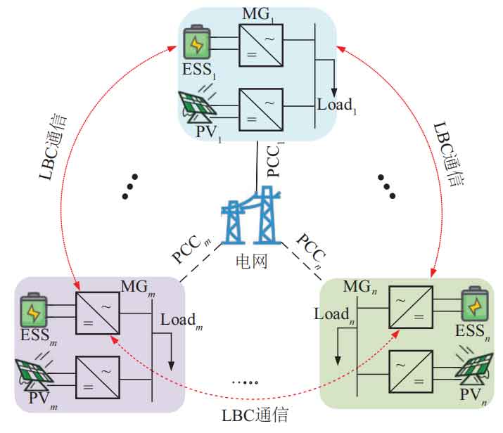
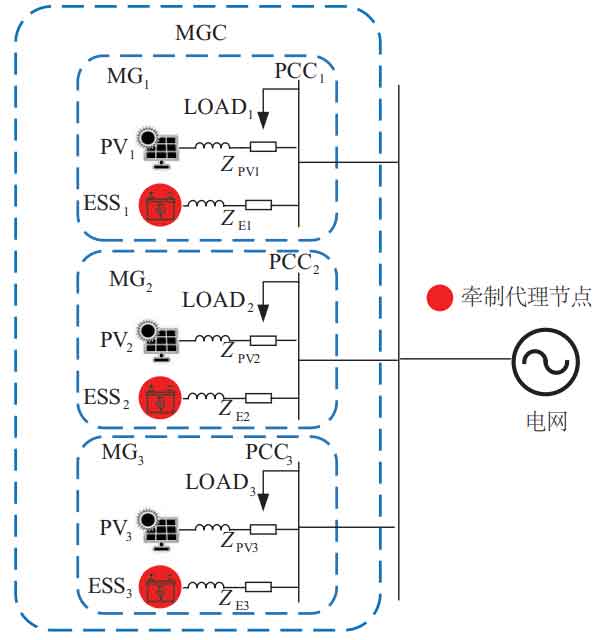
The overall structure of the MGC system is shown in Figure 1. This article uses a low bandwidth communication (LBC) network to connect adjacent energy storage devices and photovoltaic power generation units, and exchange information with each other. Each MG in MGC is connected to the power grid through its common coupling point (PCCi, i=1,2,…, n). Each MG includes DGs, ESS, and loads. List a microgrid system consisting of n microgrids, where m represents the m-th microgrid group and the m-th other unit, and n represents the n-th microgrid group and the n-th other unit.
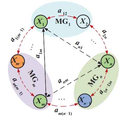
Each DG and ESS in the communication network can be considered as an agent. The physical model of the MGC system with sparse communication network in Figure 1 is transformed into the weight graph in Figure 2, and then the weight graph is abstracted as an adjacency matrix. On this basis, a coordinated control scheme based on restraint is adopted to control the variables to reach the predetermined value.
Distributed containment control methods are commonly used for coordination and unification between multi node networks. By using the local and adjacent node information of the controller in each region, the controlled target state variable converges to the same state variable, thereby achieving variable containment control. Taking first-order integration as an example, the state equation is:
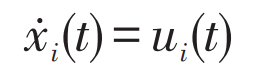
In the formula: t – time t; Xi – state variable of agent i; Ui (t) – The control objective variable of node i, which can be described by distributed containment theory as:
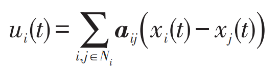
In the formula: aij – Communication network coupling matrix; Ui – Node i and j information state interaction controller; Xi – Status information of the i-th node; Xj – Status information of the jth node; Ni – Number of communication network nodes.
The first order distributed constraint control problem is transformed into solving the ui, so that the xi of all states converges to a common equilibrium point. Sometimes the system state needs to converge to the set external control input, rather than the initial value of the system, so proxy nodes need to be introduced. The agent transmits control signals to the subsystem and updates the state function to:

In the formula: aij – communication topology; G – check the proxy matrix, with all non proxy nodes having a gain of 0; Gm – the restraining gain of the restraining agent; X ˉ —— Control the expectations of the agent; When i ϵ When g, gm=1 or gm=0, the proxy control controlled variable converges to the external control signal x ˉ , Achieve consistency of MGC information.
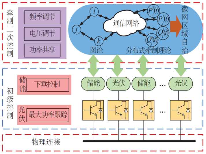
The overall strategy diagram of MG control is shown in Figure 3, including primary control and secondary control strategies. The primary control of the energy storage system is a droop strategy, and the photovoltaic power generation system uses maximum power tracking control to output maximum power. The communication network is constructed using graph theory. On the basis of traditional droop control, secondary control is added to participate in voltage, frequency regulation, and power sharing, thereby achieving high autonomy in the MG region.
2.Energy storage unit containment coordination secondary control strategy
2.1 Traditional Sag Control
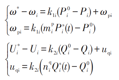
The voltage and frequency reference values of the ESS are obtained by the droop controller:
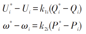
In the formula: U * i ω* —— Voltage and frequency reference values for distributed energy and energy storage units, V, Hz; P * i, Q * i – rated active power and rated reactive power, kW, kvar; K1i, k2i – active and reactive droop coefficients; Ui ω I – Real time values of frequency and voltage, V, Hz; Pi, Qi – Real time values of active and reactive power, kW, kvar.
Sag control can participate in the distribution of output power of distributed power sources, making it easy to achieve plug and play of distributed power sources. However, the droop control characteristic can cause a drop in system voltage and frequency, so secondary control needs to be introduced. To achieve accurate power sharing in the MGC system and ensure rapid recovery of system frequency and voltage to stability, a restraining and coordinating secondary control strategy is proposed.
2.2 Secondary controller design
The structure of an MGC system composed of multiple MGs is relatively complex, requiring fast communication and coordinated control between systems. The theory of distributed containment control is considered to have important research significance in MGC systems, which can achieve integrated control of MGC, etc. The equation for an n-dimensional linear cluster synchronous coupling system with external controllers added is:

In the formula: k – system coupling strength.
To achieve power sharing for restraining agents, the external controller ui=gm (xi (t) – x ˉ) Rewritten as ui=gm (Pi (t) – P ˉ Ref) and ui=gm (Qi (t) – Q ˉ Ref). Therefore, equation (7) has been rewritten as equations (8) and (9). The expressions for the expected values of active and reactive power in equations (8) and (9) are shown in equations (10) and (11).
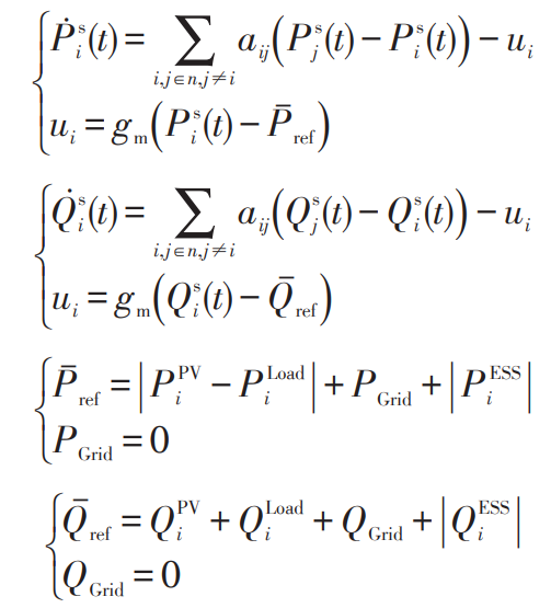
In the formula: P ˉ Ref, Q ˉ Ref – the expected values of active and reactive power controlled by the energy storage system, which are also the power conservation values of each MG system, in kW and kvar; Psi, Qsj – active and reactive power synchronization function of nodes i and j, kW, kvar; PPVi, PESSi, QPVi, QPVi – The total active and reactive power output of the i-th node’s photovoltaic and energy storage system, in kW, kW, kvar, kvar.
Simultaneously considering the positive and negative relationship between the load in MG and the output power of the photovoltaic power generation system, a high degree of regional autonomy of MG in MGC can be achieved. Each MG communicates through ESSi (i=1, 2,…, n) and maintains the safe and stable operation of the MGC system.
The primary control of ESS is a droop control strategy. When adding containment secondary control, the two correction quantities uqi and ω PI is added to the primary controller to achieve accurate power sharing and coordinated control between MGs. The secondary controller is shown in Figure 4.
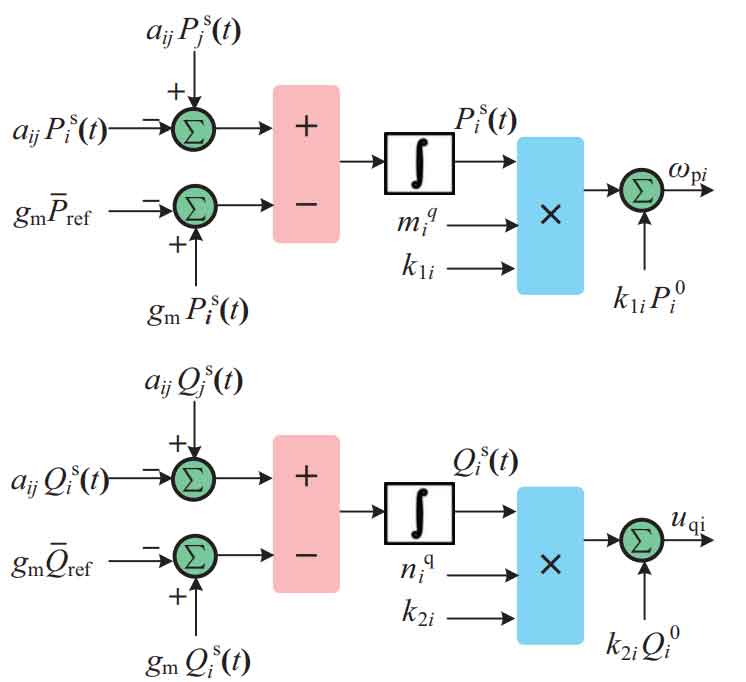
In the formula: mpi, nqi – standard normalized active and reactive capacity of the energy storage system; P0i, Q0
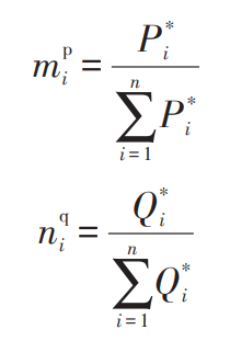
I – Set values of active and reactive power, kW, kvar. According to Figure 4, mpi and nqi in equations (12) and (13) will be pre assigned to each energy storage system node agent, and these variables can be obtained through equations (14) and (15).
2.3 Energy storage and photovoltaic control strategies
The control structure of the photovoltaic system is shown in Figure 5, where the photovoltaic array is connected to a boost converter and controlled by a maximum power point tracking (MPPT) system. MPPT uses perturbation observation method to change the voltage between photovoltaic array terminals to obtain maximum power.
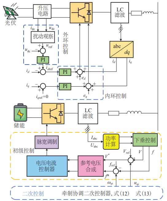
The main circuit control structure of the energy storage system is shown in Figure 5. Collect the voltage and current on the filter side, and calculate the active power P and reactive power Q through power calculation. The reference voltage signal is obtained through the power droop outer loop, and the modulation wave is obtained through voltage and current double closed-loop regulation. Finally, the control of the inverter circuit is completed through PWM modulation. The secondary control of energy storage system restraint coordination will be added to the droop control based on equations (12) and (13) ω Two correction quantities, pi and uqi, are used to quickly communicate between MGs, thereby achieving consistency in system power.
2.4 Stability analysis
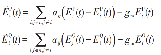
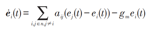
To analyze the stability of the constraint coordination control strategy proposed in this article, the Lyapunov function is used to analyze the stability of the MGC system based on constraint coordination quadratic control. Make EPi=Psi (t) – P ˉ Ref and EQi=Qsi (t) – Q ˉ Ref represents the error between the actual output of the restraining agent and the expected value, and rewrites equations (8) and (9) as:
The error can be expressed in vector form ei=[EPi, EQi] ^ T as:
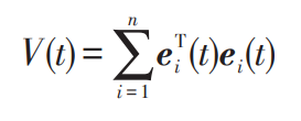
By constructing Lyapunov candidate functions (equation (19)), the stability of the quadratic control system based on constraint coordination is determined.
Its time derivative is:
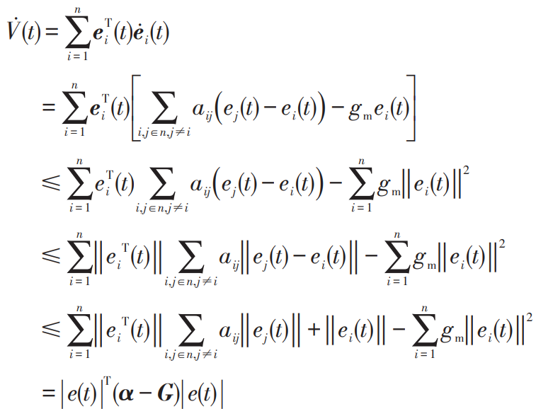
In the formula: G – the restraining gain of each energy storage unit, G=diag (g1, g2,…, gm); α —— The communication coupling matrix between nodes, α = Aij (i, j ∈ n, i ≠ j).
In equation (20), according to α – Determine whether G is negative definite and whether the time derivative of the Lyapunov function has a globally asymptotically stable equilibrium point. If α – G is negative definite, meaning there is a globally asymptotically stable equilibrium point, and the synchronization function will be consistent with the expected power value of the restraining agent system.
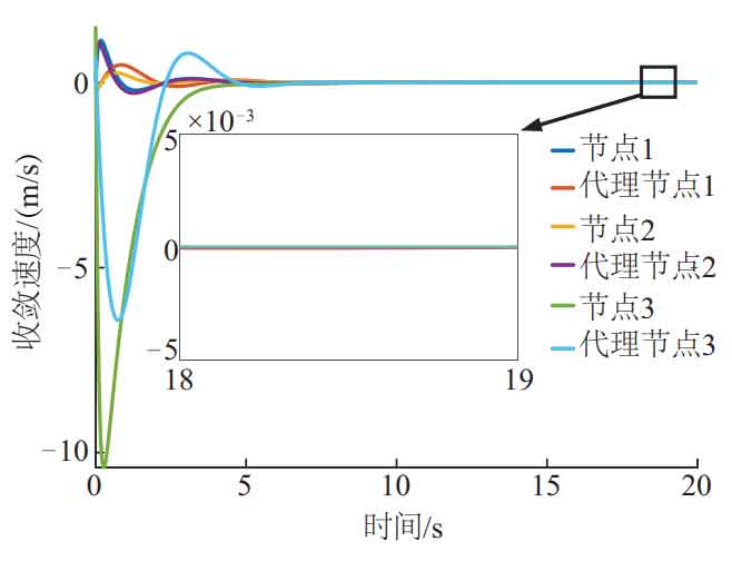
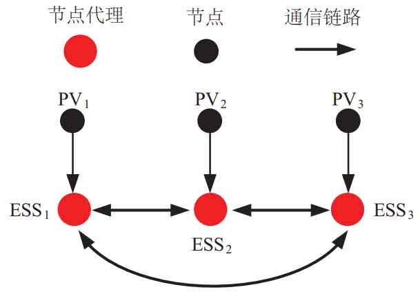
Verify the stability of the proposed scheme through Matlab simulation. Consider the MGC system with three energy storage units and construct a communication network model, as shown in Figure 6. Construct a communication coupling matrix based on the communication network model in Figure 6 α、 G. The maximum characteristic value obtained is less than 0, α – G is a negative definite matrix. As shown in Figure 7, the proxy node and node achieve information consistency at t=8 s. In summary, the system has a globally asymptotically stable equilibrium point. The MGC system proposed in this article based on constraint coordination secondary control can ensure the safety and reliability of the system.
3.Analysis of experimental results
To verify the feasibility of MGC based on constraint coordination secondary control in practical situations, a StarSim based semi physical simulation MG experimental platform was built, as shown in Figure 8. This article conducts three experimental studies, scenario 1 verifies the basic control performance of the proposed control strategy, scenario 2 and scenario 3 respectively verify the control performance under single-phase current short circuit fault and communication link fault conditions.
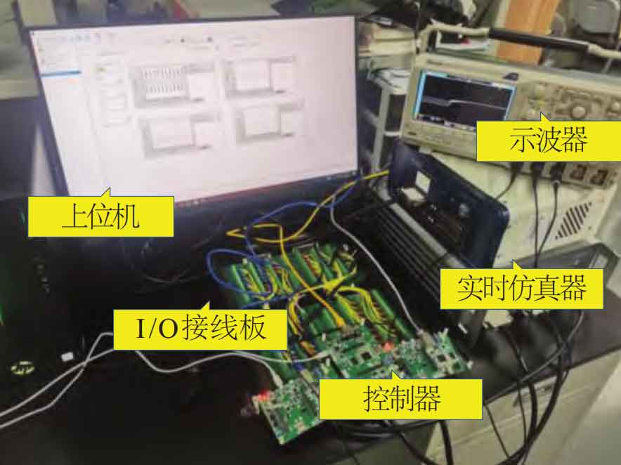
Figure 9 shows the physical unit configuration of the MGC system, including 6 lines and 3 MGs. The ESS in the MG is set to restrain the coordinated control agent. The basic electrical parameters of the MGC system are shown in Table 1.
3.1 Adding Secondary Control
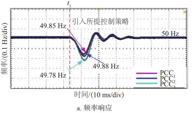
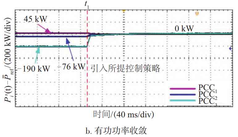
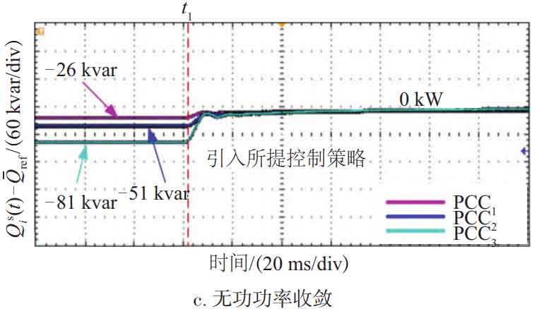
Scenario 1 tested the operational performance of three MG systems when adding secondary control for constraint coordination. Figure 10 shows the operational effect of the proposed containment coordination secondary control when t=33 ms. As shown in Figure 10a, when t=0-33 ms and the proposed secondary control strategy is added, the frequency on the PCC side fluctuates to 49.78 Hz and stabilizes to 50 Hz after 40 ms. As shown in Figures 10b and 10c, when t=0-130 ms, there is power interaction between MG and the power grid, because the active output of the photovoltaic power generation system in MG cannot meet the load; When t=130 ms, the proposed control method is added, and the interaction values of active and reactive power on the PCC (i i=1, 2, 3) side converge to 0, meeting the convergence conditions in equations (8) to (11), and meeting the expected values of the proposed control strategy. This achieves no power interaction between MGC and the power grid, meaning that each MG region is autonomous, and meets the national standards for grid frequency and voltage fluctuation amplitude.
| Parameter Name | Parameter symbols | Value |
| Grid voltage/V | V | 380 |
| System frequency/Hz | f | 50 |
| Terminal voltage V of photovoltaic system | Vpv-dc | 1000 |
| Energy storage system terminal voltage/V | VESS-d | 968 |
| Rated power of photovoltaic system/MW | Pr-PV | 1 |
| Rated power of energy storage system/MW | Pr-ESS | 0.5 |
| Filter inductance, capacitance/mH, μ F | L, C | 1.8,25 |
| Voltage loop ratio and integration coefficient | Kvp ,Kvi | 4,25 |
| Current loop ratio and integration coefficient | Kip,Kii | 0.2,15 |
| Line 1: Line impedance of PV1/Ω, mH | Zpv1 | 0.01,2 |
| Line 2: Line impedance of ESS1/Ω, mH | ZE1 | 0.01,2 |
| Line 3: Line impedance of PV2/Ω, mH | Zpv2 | 0.01,1 |
| Line 4: Line impedance of ESS2/Ω, mH | ZE2 | 0.01,1 |
| Line 5: Line impedance of PV3/Ω, mH | Zpv3 | 0.02,2 |
| Line 6: Line impedance of ESS3/Ω, mH | ZE3 | 0.02,2 |
3.2 Impact of single-phase current short circuit fault on the system
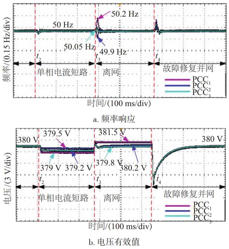
Scenario 2 tested the impact of single-phase current short circuit faults on the MGC system based on restraint coordination secondary control. In this scenario, MG is always in the secondary control mode of containment coordination. As shown in Figure 11, when t2=100 ms, a current short circuit fault occurs on the grid side; At t3=400 ms, the MGC system was disconnected from the power grid due to a fault; At t4=650 ms, the fault was repaired and reconnected to the power grid.
3.3 Impact of communication link failures on the system
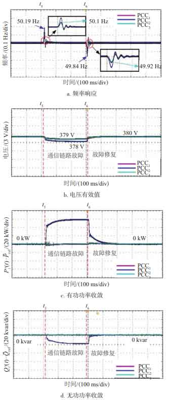
As shown in Figure 12, when t=200 ms, the communication link in the communication network fails, meaning that ESS2 is disconnected from the overall communication network; At t=500 ms, the ESS2 communication link fault was repaired and the communication network returned to normal state. According to Figure 12, when the communication link of ESS2 fails, the voltage on PCC2 decreases by 2 V, and the voltage on PCC1 and PCC3 decreases by 1 V; The frequency fluctuation amplitude on PCC2 is 0.19 Hz, and the frequency fluctuation amplitude on PCC1 and PCC3 is 0.1 Hz. After a brief adjustment, it quickly returned to a stable state. When t=t6, the communication link is restored, and the system can quickly achieve frequency and voltage control objectives. When communication failure occurs in ESS2, the convergence conditions of equations (8) to (11) are not met. As shown in Figures 12c and 12d, there is interaction between active and reactive power on the PCC2 line. The failure of the ESS2 communication link did not affect the system, indicating that the regional autonomy effect of the system is good. After the communication link is restored, the frequency and voltage on the PCC quickly return to a stable state, while the active and reactive power also converge to a stable state.
4. Conclusion
For an MGC structure composed of multiple MGs, this paper proposes a method of implementing MG regional autonomy using distributed constraint coordination secondary control. Firstly, design and establish an MGC system model based on sparse communication networks. In MG, the photovoltaic system adopts the MPPT control strategy, with droop control as the primary control of the energy storage system and restraining control as the secondary control of the energy storage system. Secondly, a detailed explanation was provided on verifying the stability of the system by constraining coordinated control and constructing Lyapunov functions. Finally, an MGC experimental platform was established to evaluate the performance of this method. The experimental results show that when the power grid side is affected by faults and the communication link fails, the maximum fluctuation of the system frequency does not exceed ± 0.2 Hz, and the maximum voltage drop is 2 V. This meets the national standards for power grid frequency and voltage fluctuations, achieving a high degree of autonomy in the MGC region. The system maintains good control effect and has good scalability.