
Abstract:
The design of the cooling system for a 200kW flywheel energy storage power vehicle, emphasizing the integration of shelter air conditioning and axial flow fans for efficient heat dissipation. The cooling calculations are meticulously conducted, ensuring reliable operation under various environmental conditions. The article highlights the importance of ventilation and heat dissipation in maintaining the optimal performance of flywheel energy storage systems.
Keywords: Flywheel energy storage, ventilation and heat dissipation, shelter air conditioning, axial fan, cooling system design
1. Introduction
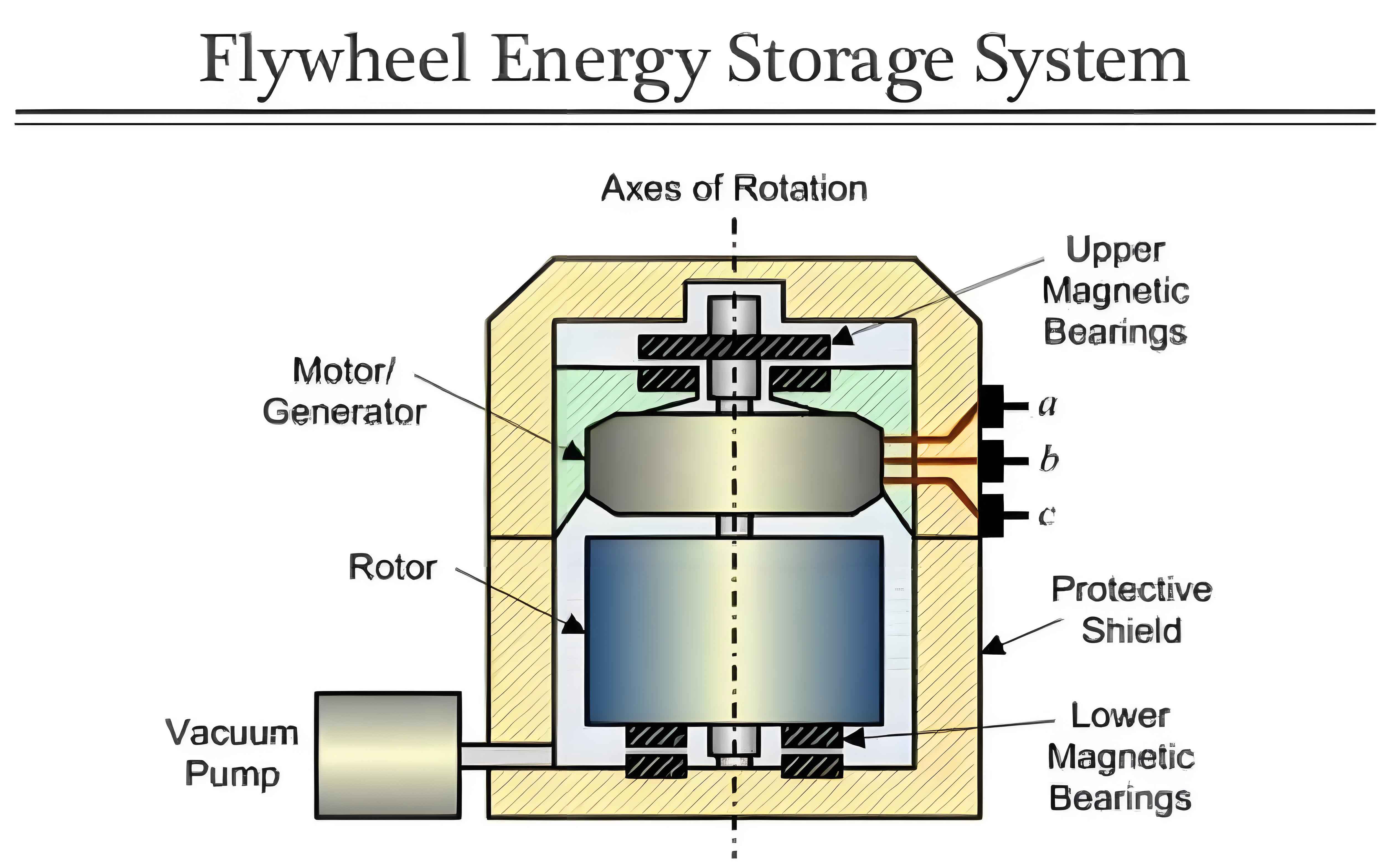
Flywheel energy storage is an advanced physical energy storage technology originating from aerospace applications. It converts electrical energy into mechanical energy by driving a flywheel to rotate at high speeds and, when needed, converts the stored mechanical energy back into electrical energy through flywheel inertia to drive a generator (i.e., flywheel discharge). Unlike other battery technologies, flywheel energy storage excels in short-duration, high-frequency, and high-power charging and discharging capabilities, primarily used in grid frequency regulation, renewable energy station integration, rail transportation, and high-power Uninterruptible Power Supplies (UPS).
The 200kW flywheel energy storage power vehicle serves as an emergency uninterruptible power supply, providing mobile outdoor power solutions. It consists of a vehicle chassis, a 300kW diesel generator set, a cabin, a 200kW flywheel energy storage device, a 200kW UPS cabinet, an ATS cabinet, a quick start cabinet, an electrical control system, a noise reduction system, an intake and exhaust ventilation system, air conditioning, hydraulic supports, a hydraulic cable reel, mains input cables, and output cables. This vehicle can achieve online emergency uninterrupted switching of a 200kW load and an independent diesel generator set rated output of 300kW power supply mode.
Table 1: Overview of the 200kW Flywheel Energy Storage Power Vehicle
| Component | Description |
|---|---|
| Vehicle Chassis | Supports the entire system |
| Diesel Generator Set | 300kW output |
| Cabin | Dimensions: 8700mm×2420mm×2620mm |
| Flywheel Energy Storage Device | 200kW capacity |
| UPS Cabinet | 200kW capacity |
| ATS Cabinet | Automatic Transfer Switch |
| Ventilation System | Intake and exhaust for cooling |
| Air Conditioning | For cabin temperature control |
2. Working Principle of the Flywheel Energy Storage Power Vehicle Cooling System
The heat generation in a flywheel energy storage power vehicle is influenced by solar radiation, equipment heat dissipation, and ventilation volume, especially in complex outdoor environments with varying meteorological conditions. Therefore, the design of the cooling system is crucial. The ventilation and cooling system not only provides a comfortable temperature environment for the cabin staff but also ensures reliable operation of equipment such as the flywheel energy storage device and UPS at optimal temperatures. The cabin temperature should be maintained around 25°C, with adequate ventilation for the flywheel energy storage device and UPS.
Figure 1: Ventilation Side View of the 200kW Flywheel Energy Storage Power Vehicle Cabin
<img src=”image_placeholder_side_view.png” />
Figure 2: Ventilation Top View of the 200kW Flywheel Energy Storage Power Vehicle Cabin
<img src=”image_placeholder_top_view.png” />
Figure 3: Ventilation Diagram of the 200kW Flywheel Energy Storage Device
<img src=”image_placeholder_flywheel_ventilation.png” />
Figure 4: Ventilation Diagram of the UPS
<img src=”image_placeholder_ups_ventilation.png” />
3. Design of the Flywheel Energy Storage Power Vehicle Cooling System
3.1. Shelter Air Conditioning Load Estimation
3.1.1. Cabin Parameters
The cabin has an overall outer dimension of 8700mm × 2420mm × 2620mm, with a flywheel energy storage cabin inner dimension of 2665mm × 2320mm × 2455mm. The ambient temperature ranges from -40°C to +46°C, with a maximum radiant intensity of 1120W/m² ± 10%. The cabin interior temperature is set at 25°C. The heat generation from the flywheel energy storage device is 0.6kW, and the UPS cabinet generates 1kW of heat. The cabin accommodates two staff members.
Table 2: Air Conditioning Parameters
| Parameter | Value |
|---|---|
| Rated Cooling Capacity | 8000W |
| Rated Cooling Consumption Power | 4000W |
| Electric Heating Device Consumption Power | 6000W |
| Inner Side Circulation Airflow | 1200m³/h |
| Indoor Noise | 65dB(A) |
| Weight | 180kg |
| Operating Environment Temperature | -45°C to 55°C (Cooling: 18°C to 55°C) |
3.1.2. Thermal Load Calculation
The thermal load calculation includes the following components:
- Equipment Heat Generation (Q11): 1600W
- Cabin Heat Storage (Q12): 2498.58W
- Cabin Air Heat Load (Q13): 904.5W
- Solar Radiation Heat (Q14): 435.86W
- Fresh Air Heat Load (Q15): 605W
- Staff Heat Load (Q16): 300W
The total thermal load (Q热) is calculated as:
Q热 = Q11 + Q12 + Q13 + Q14 + Q15 + Q16 = 6343.94W
With a selected air conditioning unit of 8000W, there is a 26% margin, ensuring the cabin temperature can drop from 46°C to 25°C within 30 minutes.
3.1.3. Cooling Load Calculation
The cooling load calculation includes:
- Cabin Heat Storage (Q21): 2498.58W
- Cabin Air Cooling Load (Q22): 2799.61W
- Fresh Air Cooling Load (Q23): 1872.65W
The total cooling load (Q冷) is:
Q冷 = Q21 + Q22 + Q23 – Q11 – Q16 = 3978.73W
A 7000W air conditioning unit is sufficient to raise the cabin temperature from -40°C to 25°C within 30 minutes.
3.2. Ventilation and Heat Dissipation Design
The main heat-generating equipment in the control cabin are the flywheel energy storage cabinet and the UPS cabinet. Manual louvers are installed near the cabinet intake to increase airflow. Exhaust ducts are added at the cabinet exhaust vents, leading to the cabin exhaust louvers equipped with axial flow fans for faster exhaust.
Table 3: Ventilation Parameters
| Component | Ventilation Rate | Axial Fan Model | Airflow |
|---|---|---|---|
| Flywheel Energy Storage Cabinet | 100m³/min (6000m³/h) | YWF-4D-500 | 8500m³/h |
| UPS Cabinet | 75m³/min (4500m³/h) | YWF-2D-400 | 6480m³/h |
4. Conclusion
The ventilation and cooling system is a vital component of the flywheel energy storage power vehicle, directly impacting the cabin’s performance and economic efficiency. This design combines theoretical knowledge with practical applications, utilizing heat balance principles and aerodynamic theory. Since its delivery in December 2021, the flywheel energy storage power vehicle has performed well in multiple power supply guarantee tasks, including summer power supply activities in Sichuan and Gansu, demonstrating excellent ventilation and heat dissipation within the cabin and reliable power supply.