
At present, for the control of solar inverters, the classic double closed-loop control structure voltage outer loop control is usually used to determine the reference value of the current, while the current inner loop control is used to achieve fast tracking of the current reference value. There are usually two types of outer loop control, one is decoupling control of active and reactive power, and the other is decoupling control of DC bus voltage and reactive power. The research is based on the latter.
Fix the d-axis of the d-q coordinate system on the voltage vector Up at the connection point, i.e. Upd=Up, Upd=0. The cross-sectional power relationship of the solar inverter connection point after equal power change is shown in the formula:
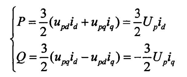
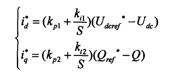
According to the formula, controlling id and iq is equivalent to controlling the power of the solar inverter. When the active power transmitted on the DC side of the solar inverter is not balanced with the active power injected on the AC side, the sample delivery will cause the DC side bus voltage to be unstable. In order to maintain the assumed value of the DC side bus voltage, it is necessary to adjust and control the active current. A typical PI outer loop control design is as follows:
From the formula, it can be seen that id and iq are mutually coupled, that is, id and iq are not only affected by the control output d, q-axis voltage (md/2) Udc, (mq/2) Udc, and connection voltage of the solar inverter, but also by the coupling parameters of each other ω Liq ω The changes in Lid are related, which poses difficulties for the control of solar inverters. Usually, the current feedforward decoupling control method is used for control unit design, introducing a PI control unit and designing an inner loop control unit based on the formula:
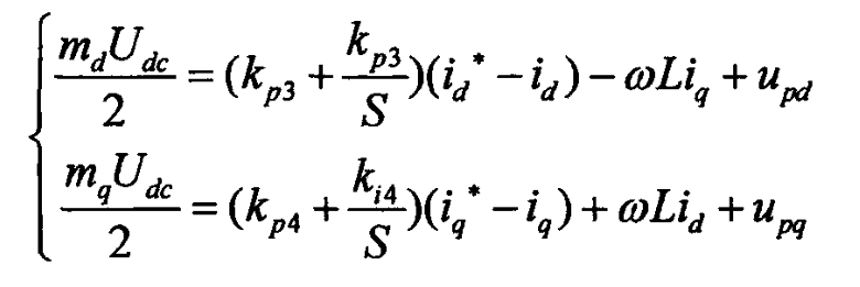
Clearly, in a synchronous rotating coordinate system, the d-q axis components output by the solar grid connected inverter are coupled to each other. For the control method of solving the interdependence between dq axes, it is usually to use the feedforward variable- ω Liq (s) and+ ω Lid (s) is introduced into the output AC voltage of the solar grid connected inverter to align it with the coupling term+ ω Liq (s) and- ω Lid (s) cancel each other out, and the system model is transformed into two independent and completely equivalent parts, thereby achieving complete decoupling between axes. In fact, feedforward decoupling is just an open-loop decoupling scheme that weakens coupling, and it is difficult to truly achieve complete decoupling because the decoupling performance is closely related to the compensation parameters of the control system.
The main control objective of solar grid connected inverters is to ensure that the system can transmit energy according to the predetermined active and reactive power, thereby ensuring the quality of electrical energy. In a typical dual loop control system, the outer loop control system is usually mainly used to achieve power transmission control. The outer loop is used to track the given maximum active power and the set reactive power, and obtain the reference values of the inner loop reactive current and active current. The inner loop is used to track the reference current given by the outer loop, And achieve SPWM control signal driving.
In the d-q coordinate system, the instantaneous active power p and reactive power q of the photovoltaic grid connected system are calculated using the formula:
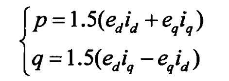
When based on grid voltage d-axis orientation, eq=0, then p=1.5edid, q=1.5eqiq. If the changes in grid voltage are not taken into account, i.e. when ED is fixed and unchanged, there is a positive proportional relationship between the active power p and reactive power q of the solar inverter device and the components of the current on the d and q axes. Under the condition of ensuring a constant system voltage, the power transmission of the solar inverter can be controlled by controlling id and iq.
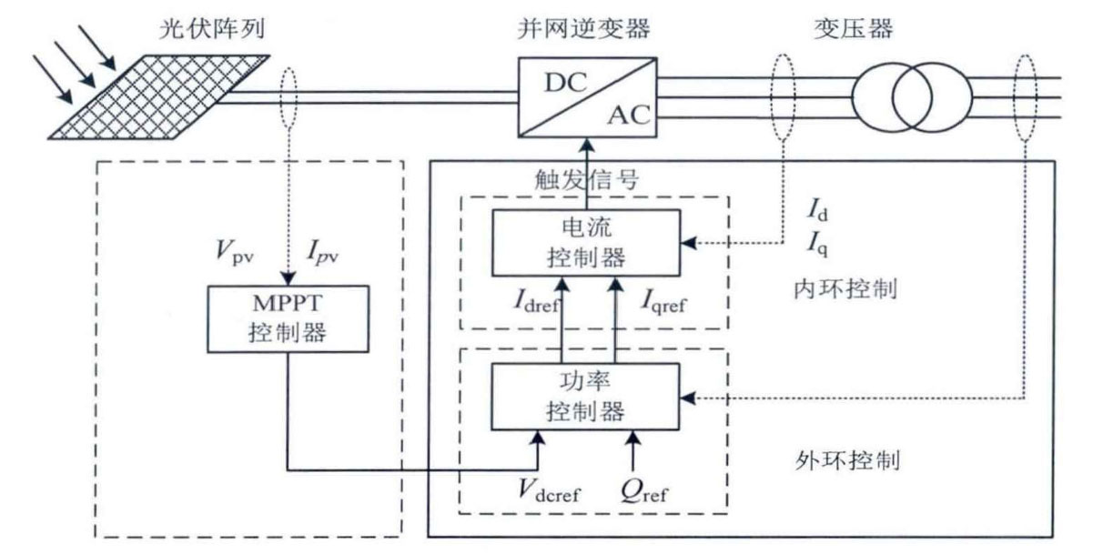
As mentioned earlier, the following figure provides a block diagram of the analysis model for solar inverters.