
1. Maximum power point tracking control
From the P-I characteristic curve of solar cells, it can be seen that there is a maximum power point during the operation of solar cells. In order to improve the efficiency of solar photovoltaic grid connected power generation systems, it is best to control the working point of solar cells near their maximum power point, or even at the maximum power point. This proposes the Maximum Power Point Tracking (MPPT) control for solar photovoltaic grid connected power generation systems.
1.1 Principle of Maximum Power Point Tracking Control
From the basic knowledge of circuits, it can be seen that in general linear circuits, as long as the load is appropriately adjusted to make the adjusted external resistance R0 equal to the internal resistance Ri in the power supply, the maximum load power can be achieved. Figure 1 shows the circuit diagram of the most basic linear system:
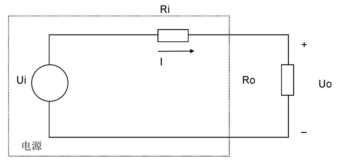
However, the method shown in the above diagram that utilizes equal internal and external resistance values to achieve maximum power output is only applicable to power supply systems with constant internal resistance. However, the internal resistance value of photovoltaic cells is influenced by various factors such as load, temperature, and light intensity, so this method is not applicable.
The method used here is to control the opening and closing of the DC/DC circuit transistors, thereby controlling the DC output of the solar photovoltaic array to always work near the maximum power point shown in Figure 4, achieving the maximum output power of the solar photovoltaic grid connected power generation system. The specific operation can be analyzed according to Figure 4:
(1) When the working voltage of the photovoltaic cell is to the left of the maximum power voltage point Um, the actual working voltage is less than Um, so the output voltage of the cell should be increased to approach the maximum power point.
(2) When the working voltage of the photovoltaic cell is to the right of the maximum power voltage point Um, the actual working voltage is greater than Um, so the output voltage of the cell should be reduced to approach the maximum power point.
1.2 Several Common MPPT Control Methods
The solar photovoltaic grid connected power generation system is greatly affected by external factors such as light and temperature during operation. Whenever the environment changes, the output state of the solar cell will also change accordingly. In addition, solar cells themselves have low photovoltaic conversion efficiency, and the purpose of green energy is to save costs and improve efficiency. Therefore, how to make solar cells work at their maximum operating point has always been the focus and core of research in solar photovoltaic grid connected power generation systems. We will introduce several main maximum power tracking algorithms and analyze them to some extent.
1.2.1 Interference measurement method
The interference measurement method, also known as the power disturbance observation method, is based on the principle that under the normal operation of the solar cell, the current output power of the working state is first measured, and the measurement data is obtained. After obtaining the measurement data, an additional one is added to the current output voltage of the solar photovoltaic cell Δ U. Afterwards, measure the output power of the photovoltaic cell again. If the output power obtained from the second time is greater than the first time, it indicates that the output voltage is still on the right side of the maximum power point. Continue the above operation until the output power approximates a stable value, which can be used as the approximate maximum power point; If the output power measured in the next measurement is less than the previous one, it indicates that the maximum power point is to the left of the current output voltage position. At this point, the added Δ U becomes- Δ U. Repeat the operation until the output power approximates a stable value, and use it as the maximum power approximation point. It can be understood in conjunction with Figure 2.
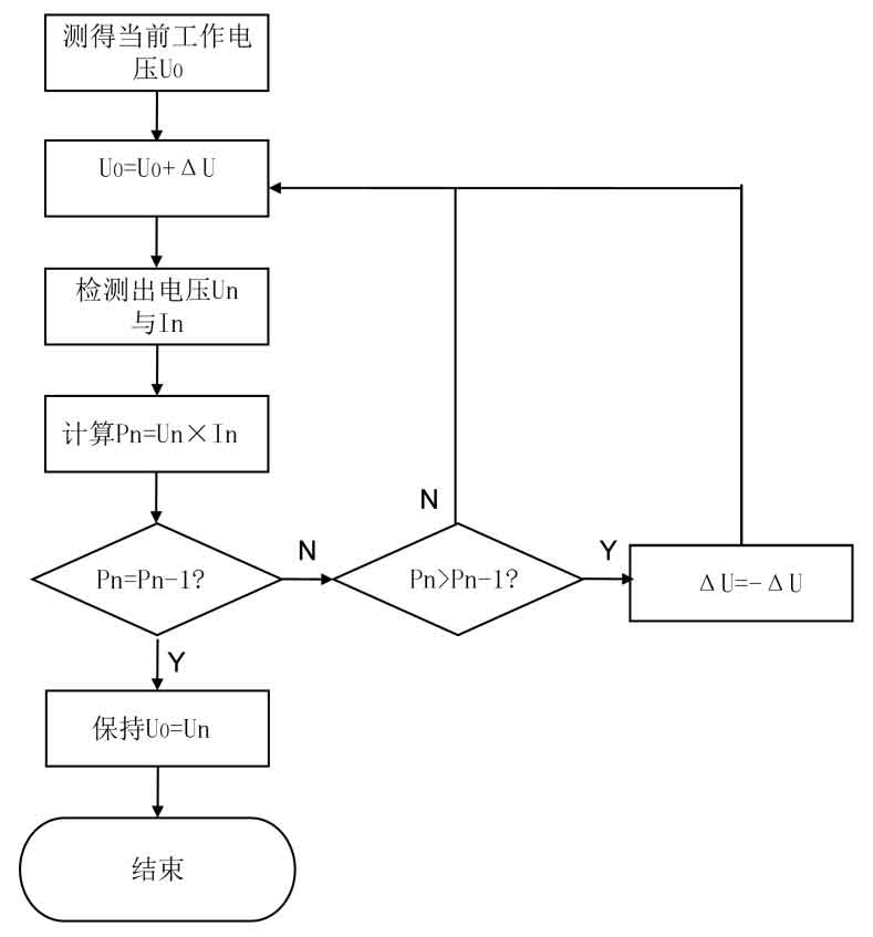
The control process of interference measurement method is shown in the above figure, and the control method is simple and easy to implement. The measurement accuracy requirements for each parameter are not high, making it suitable for situations with stable environmental changes.
However, its drawbacks are also very obvious. It is necessary to continuously judge whether the applied voltage is at the voltage of the maximum power point. As a result, the working voltage of the solar cell will fluctuate continuously, resulting in a certain amount of power loss. And from the working principle of the interference measurement method, it can be seen that it is a process of continuously increasing the disturbance voltage until it approaches the maximum power point. Therefore, it is difficult to set such a disturbance voltage so that the method can achieve the target voltage as soon as possible while ensuring the accuracy of the achieved voltage. If the disturbance voltage is too large, although it can quickly reach steady state, the power loss will also increase and the accuracy will decrease; If the disturbance voltage is too small, although power loss will decrease and accuracy will increase, the speed of reaching steady state will be very slow.
1.2.2 Incremental conductivity method
The interference measurement method described above is to continuously change the output voltage of the solar cell, and then measure the power values before and after the change, so that the solar photovoltaic grid connected power generation system continuously approaches the maximum power point, thereby achieving maximum power point tracking control. But according to its principle, it can be seen that the initial increase Δ When U is used, the direction of voltage increase or decrease is not known, which can result in unnecessary loss of time and power energy. So now we introduce a conductivity increment method to overcome this drawback.
The principle of incremental conductivity method is as follows:
According to the basic knowledge of circuits, the output power of solar cells is:
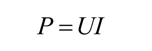
Taking the derivative of U on both sides of the equation yields:
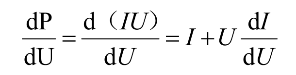
Based on the P-U curve in Figure 4 and mathematical knowledge, it can be inferred that there is dP/dU=0 at the maximum power point, where U=Um; When dP/dU>0, there is UUm. By combining these three situations with the formula, the following conclusion can be drawn:
When U=Um:
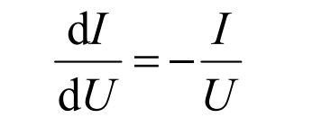
When U>Um:
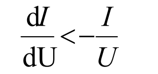
When U<Um:
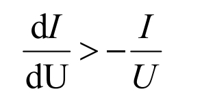
Combining the above formula, when dU=0, if dI=0, the solar cell is at its maximum power point and does not need to be adjusted; When dI ≠ 0, the working point of the solar cell needs to be adjusted to a certain extent, and the specific adjustment should be determined based on the positive or negative dI. When dU ≠ 0, the current output voltage can be adjusted according to the formula to make the value of the formula approach 0, thereby maintaining the operation of the solar photovoltaic grid connected power generation system at the maximum power point.
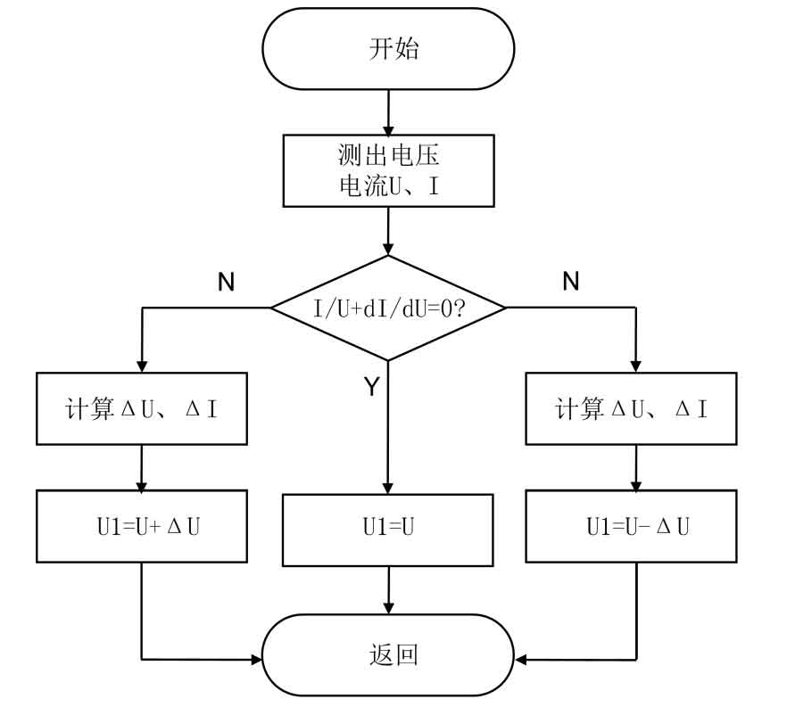
From the above explanation, it can be seen that the conductance increment algorithm operates based on slope, so even when there are significant changes in the external environment, it can quickly restore the solar cell to its maximum power point and operate smoothly. There is no need to consider the issue of setting the interference amount in the previous interference measurement method, which is suitable for situations where the external environment changes frequently. However, this method also has certain drawbacks. Due to its ability to adapt to frequently changing external environments, it requires high hardware requirements and highly sensitive sensors, which in some ways increases the cost of solar photovoltaic grid connected power generation systems. Moreover, the algorithm of incremental conductance method is also very complex, making it difficult to design.
1.2.3 Fixed voltage control method
From Figure 4, it can be seen that with little temperature change and only considering light as the main factor affecting the solar photovoltaic grid connected power generation system, the maximum power point of the solar cell is always located on a straight line perpendicular to the horizontal axis, so its corresponding working voltage remains basically unchanged. The fixed voltage control method, as the name suggests, is to control the output voltage of the solar cell near such a fixed voltage value, thereby approximating the maximum power control of the solar photovoltaic grid connected power generation system.
The principle of this method is very simple and has the advantages of high reliability and easy algorithm design. However, it is obvious that it ignores the influence of temperature changes on solar cells, making it unsuitable for areas with severe temperature changes and large day night temperature differences. Moreover, the maximum power point found by this method is only approximate and not accurate, precisely because solar photovoltaic grid connected power generation systems will lose a considerable amount of energy. However, due to its high stability and reliability, it can still be used in some solar photovoltaic grid connected power generation systems with low precision requirements.
1.3 Implementation of MPPT Control in DC/DC Circuits
As mentioned in previous chapters of this article, in order to achieve maximum load power in the basic circuit, it is only necessary to keep the external resistance in the circuit consistent with the internal resistance of the power supply. Of course, using this method to maximize power is generally only applicable to linear systems. In solar photovoltaic grid connected power generation systems, although the output characteristics of photovoltaic cells are nonlinear like DC/DC conversion circuits, they can be considered as linear systems under certain conditions. In this case, only the equivalent resistance of the DC/DC conversion circuit needs to be adjusted to be the same as the internal resistance of the photovoltaic cell, achieving maximum power output. As for the method of adjusting the resistance, because the DC/DC conversion circuit controls the output voltage by adjusting PWM (duty cycle), the load voltage can be adjusted to half of the power supply voltage using this conversion circuit, which is equivalent to adjusting the resistance. So in practice, the maximum power can also be achieved by adjusting the voltage at both ends of the load.
Similarly, based on the Boost conversion circuit selected in this project, an improved MPPT control method can also be proposed:
The formula can be used to transform the formula for the output power of photovoltaic cells to obtain:

In the formula, P0 is the output power of the photovoltaic cell, U0 is the output voltage, IL is the output current, and D is the duty cycle of the circuit.
So it can be imagined that in the MPPT control strategy, duty cycle disturbance can be used instead of voltage disturbance, that is, using Δ D to replace Δ U. Provide a grid connected solar photovoltaic power generation system Δ After the disturbance of D, detect the change in power value Δ P. Enable Δ D and Δ Multiplying U, if the result is>0, it indicates that the working band is located to the left of the maximum power point, and the next increase in disturbance Δ D> 0; If the result of the product is<0, then the added disturbance Δ D<0. Due to the fact that this method determines the maximum power point based on the addition or subtraction of power, it is more intuitive and a good MPPT control strategy.
2. Inverter circuit control
The control of the inverter circuit is a key focus in the design of solar inverters. As more and more advanced control strategies continue to emerge, the performance of the digital signal processor (DSP), which serves as the carrier of control, is also constantly improving. The control objectives and some control methods of solar inverters will be introduced, and suitable solar grid connected control schemes will be selected through comparison and analysis. The design of DSP control circuits and chip selection will be analyzed later.
2.1 Control objectives of inverter circuits
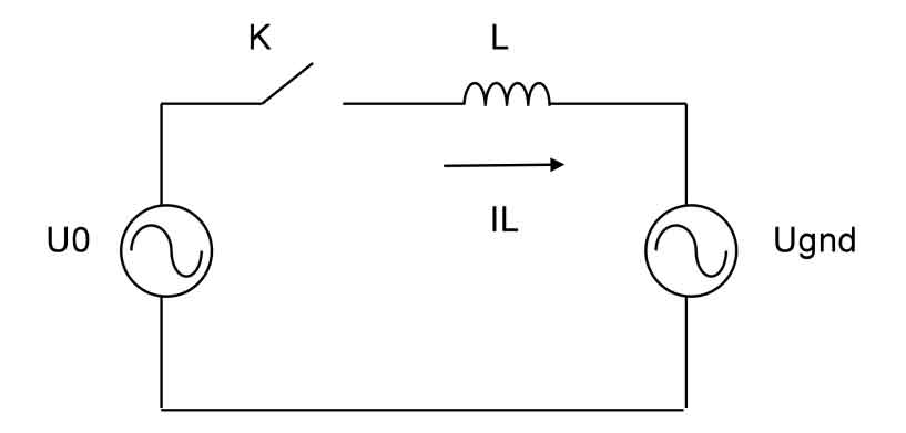
In the physical quantities in the above two figures, U0 is the output voltage of the inverter circuit, Ugnd is the grid voltage, IL is the grid connected current of the solar inverter, and L is a series inductor. As mentioned earlier, when connected to the grid, the AC power controlled by the solar inverter must have the same frequency and phase as the grid AC power, that is, the angle between the current and voltage is 0, which means the power factor is 1. So in the vector diagram shown in Figure 5, it can be seen that the grid connected current IL and the grid voltage Ugnd are on the same axis and in the same direction, indicating that the phase of the two is the same, and the grid voltage Ugnd leads the inductor voltage UL90 °
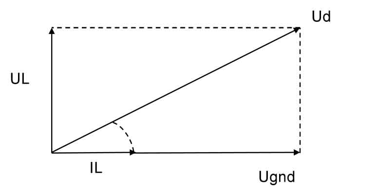
From the circuit in Figure 5, a vector equation can be obtained:
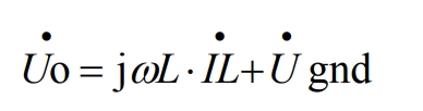
According to the formula, it can be seen that when the output current IL is kept at the same frequency and direction as the grid voltage Ugnd, there will be a phase difference between the output voltage Uo of the inverter circuit and the grid voltage Ugnd. Additionally, in the formula ω It represents the angular frequency of the power grid.
From the above analysis, it can be seen that a key task in photovoltaic grid connected power generation systems is to integrate the electricity generated by solar photovoltaic grid connected power generation systems into the grid, which is also one of the main tasks of solar inverters. The key to grid connection is to ensure that the output current is in the same frequency and direction as the grid voltage, which is the control goal of the grid connected inverter. In actual operation, in order to ensure grid connected status, IL is monitored at any time through a current sensor to ensure a power factor of 1 for grid connected power generation.
2.2 Control strategy of inverter
It can be seen that the most critical part of the control of solar grid connected inverters is the control of output current. According to vector figure 5, in order to control the output current, I can be directly controlled or the current I can be indirectly controlled by controlling the output voltage Uo. So, according to the different control objects, the control strategy of solar inverters can be divided into the following two modes:
1) Indirect current control: This is a control method that indirectly controls the grid connected current by controlling the voltage. This control method is based on the value of the current vector during grid connection, as well as the amplitude and phase of the voltage vector after pulse width modulation, combined with the operation concept of the formula for closed-loop control. Finally, the control of the current is achieved by controlling the voltage. Obviously, this control method is not complicated and does not require monitoring the magnitude of grid connected current, but it has a very strict prerequisite – the grid voltage cannot produce distortion. Obviously, in real operation, due to changes in grid load and various external factors, it is difficult to maintain a stable level of grid voltage, which will cause voltage distortion and affect the accuracy of control of solar photovoltaic grid connected power generation systems. Moreover, this method also has complex control circuits, and there may be some delay in the dynamic response of the solar photovoltaic grid connected power generation system during operation.
2) Direct current control: As the name suggests, it is to directly calculate the AC current through calculation, and then directly control the AC current by introducing AC current feedback to achieve the specified grid connected current value. In order to obtain a sinusoidal current waveform with the same frequency and phase as the grid voltage, the product of the grid voltage signal and the active current is generally taken, which assigns frequency and phase to the measured output current to generate an approximate grid connected current waveform. Then, the output current tracks this current waveform to achieve the grid connected conditions of the solar inverter. Compared to indirect current control, the control circuit of direct current control is simpler, and because of this, its dynamic response speed is also faster and the efficiency during operation is higher. Speaking of the control loop, the commonly used method in this regard is single loop or double loop control. Single loop control can adjust the waveform of the output voltage in real time, effectively suppressing the nonlinear characteristics of components and the impact of DC bus voltage fluctuations, and improving the static and dynamic characteristics of solar inverters to a certain extent. However, due to the fact that this control method only has single voltage loop control, when the load undergoes significant dynamic changes (such as sudden increase in load current), The output voltage of solar inverters will have significant distortion and slow dynamic adjustment; Double loop control is the addition of a current inner loop inside the voltage loop, as there is a current inner loop, it can effectively use the inner loop to suppress current disturbances, thus solving a considerable part of internal interference problems and simplifying the construction of the voltage outer loop.
Finally, there are several ways to modulate the waveform:
1) PWM control technology: This control technology utilizes the opening and closing of power electronic devices to transform the waveform of DC voltage into a pulse shape, and then adjusts its width and period to achieve the purpose of adjusting the waveform, changing the original voltage size and frequency. PWM technology aims to reduce the interference of low order harmonics on circuits and better regulate power.
2) SPWM control technology: SPWM control technology is currently the most commonly used in inverter controlled solar photovoltaic grid connected power generation systems. SPWM is the product of PWM wave transformation according to the sine law. The principle of this control method is to adjust the modulation pulse method based on PWM, so that the pulse width and duty cycle are arranged according to the sine law. After filtering, sine wave output can be achieved.
3) Hysteresis control technology: This technology also has a wide range of practical applications. Its working principle is to compare the input signal with the target signal, and the difference signal will be input into a comparator with hysteresis characteristics. Determine the on/off of power devices by comparing the results. The hardware structure of this control technology is simple, therefore it has a fast dynamic response speed, and it is also a closed-loop system with certain feedback regulation and guaranteed accuracy.
3. System control circuit design
In the previous chapters, the parameter design and selection of the overall structure and hardware circuit of the solar photovoltaic grid connected power generation system were introduced, as well as a simple analysis and research on control strategies. In this chapter, the functions of control and the core chips of control will be introduced, and some circuits will be designed.
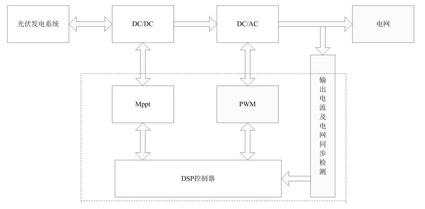
3.1 Control circuit
In the overall structural framework diagram, it can be seen that the control circuit is mainly composed of DSP control system, MPPT and PWM control, and power grid detection. The control circuit part in the diagram is cut out as shown in the following figure 6, where the dashed line is the block diagram of the circuit control part.
3.1.1 Voltage detection circuit
The grid voltage detection circuit here is located at the connection between the solar inverter and the public grid. It monitors the voltage value flowing from the photovoltaic inverter into the public grid in real time, processes it after sampling, and transmits the processed voltage signal to the DSP. The specific circuit structure and working mode are shown in Figure 7.
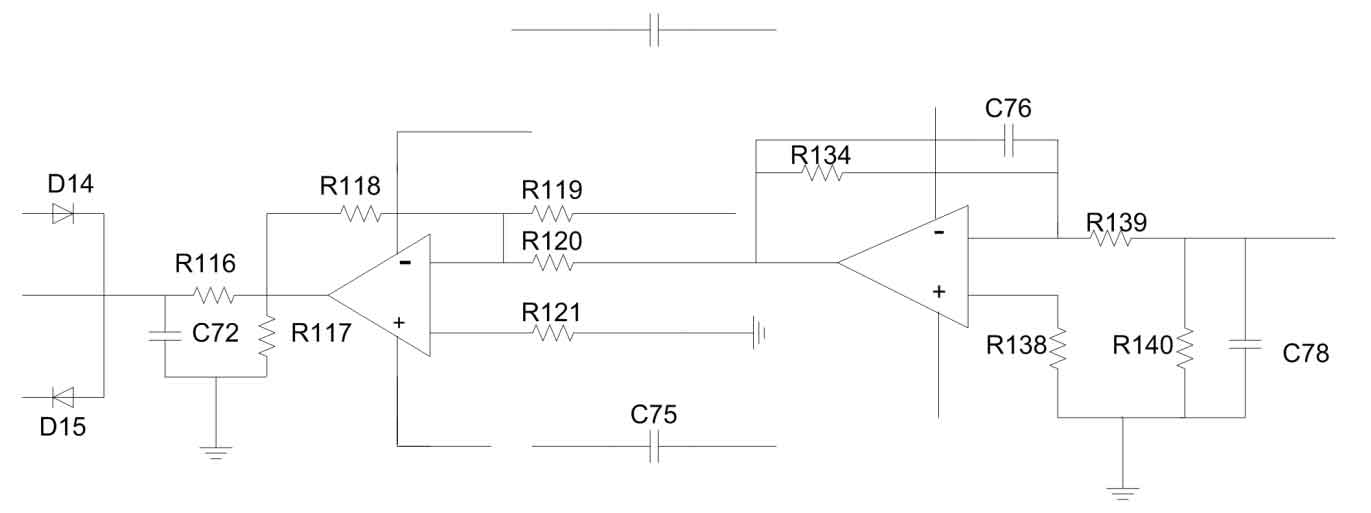
The working mode of the voltage detection circuit is that after the voltage Hall sensor located in the public power grid collects the voltage signal, the circuit will perform an operational amplifier process on its own. Due to the limited voltage range of the DSP receiver, it is necessary to increase or decrease the appropriate bias voltage on the basis of the voltage signal to avoid damage to the DSP’s internal chip. At the end of the circuit, an RC filtering circuit is also installed to enable the collected voltage signal to be received by the DSP receiver.
3.1.2 Current detection circuit
The same signal acquisition circuit also has a current detection circuit, and its specific circuit structure and working mode are shown in Figure 8.
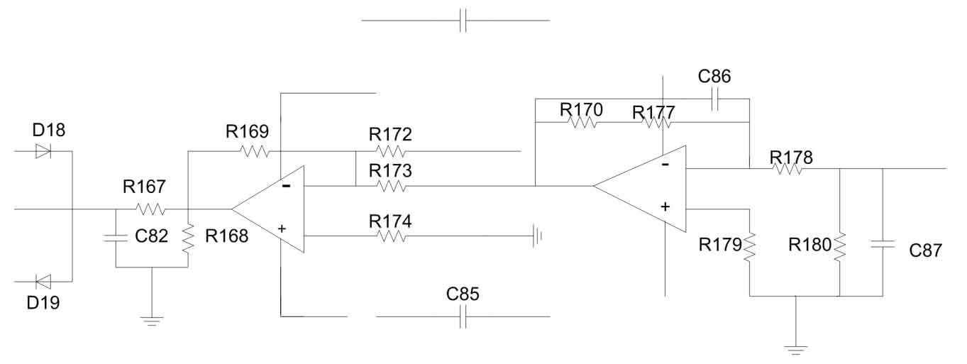
The working mode of the current detection circuit is similar to that of the voltage detection circuit, but it detects the current signal through the Hall sensor of the current. Similarly, the current signal in this circuit also needs to pass through a proportional amplifier, and then a bias voltage needs to be increased or decreased. Finally, the collected signal is transmitted to the AD port of the DSP control chip through an RC filtering circuit. This completes the process of current sampling.
3.1.3 Protection circuit
In any system, the detection circuit only provides data to protect the operation of the circuit. The protection circuit adjusts the control signal in a timely manner based on the feedback information from the circuit, ensuring that the solar photovoltaic grid connected power generation system operates in a relatively stable state. When the feedback information from a certain point in the solar photovoltaic grid connected power generation system shows abnormal phenomena, it is also necessary to send out signals in a timely manner to stop the operation of the circuit and protect the components in the circuit. In this regard, the DSP chip has such a function internally. The PDPINT and NMI modules inside the DSP can achieve interrupt circuit output, playing a protective role.
3.2 Selection and Introduction of Control Chips
The control chip model selected for this project is TMS320LF2407A. As a digital processor, it has very complete functions and can ensure the reliable operation of the solar photovoltaic grid connected power generation system. Below is an introduction to it:
| On chip resources | Functional parameter description |
| Storage resources | FLASH; 32KB; DARAM; 544KB; SARAM; 2KB |
| 2 Event Management EVA and EVB | Each contains two 16 bit general-purpose registers TIM and eight 16 bit pulse width modulation PWM channels; 3 capture units CAP, 1 set of orthogonal coded pulse QED interface |
| Universal I/O | 40 individually programmable general-purpose input/output pins GPIO, some of which belong to multiplexer pins |
| Serial interface | Fieldbus CAN2.0B, serial communication interface SCI, serial peripheral interface SPI |
| Analog interface | ADC; 16 input channels, 10 bits, with a minimum conversion time of 0.5us |
| Core modules | PLL clock transmitter, watchdog timer (WDT), enhanced interrupt controller, 5 external interrupts (2 electrical drive protection, 2 maskable interrupts, reset), 3 low-power power management modes |
The TMS320LF2407A chip is a product of TI Company. It has relatively low cost and power consumption, but in terms of performance, both running speed and stability are well guaranteed, so it has a very high cost performance ratio. The fastest computing speed of the chip can reach 40MPS, which ensures the smooth operation of the solar photovoltaic grid connected power generation system. At the same time, the chip has a 16 bit parallel multiplier and 32K flash memory, as well as a 10 bit AD converter and multiple timers with different functions. In terms of interfaces, the chip industry is also equipped with optoelectronic encoding disk interfaces, asynchronous communication interfaces, peripheral interfaces, and bus interfaces. These nearly complete functions have led to the increasingly frequent use of the TMS320LF2407A chip in controlling solar photovoltaic grid connected power generation systems, which is also the reason for choosing this chip in this project. The specific resources of the chip are shown in the table below:
According to Figure 6, the chip is directly connected to the current and voltage sampling circuit in this control circuit, and can receive feedback data from the circuit in the first time. In addition, it can be seen from the figure that the DSP chip also needs signal input from the protection module to ensure the normal and stable operation of the solar photovoltaic grid connected power generation system.
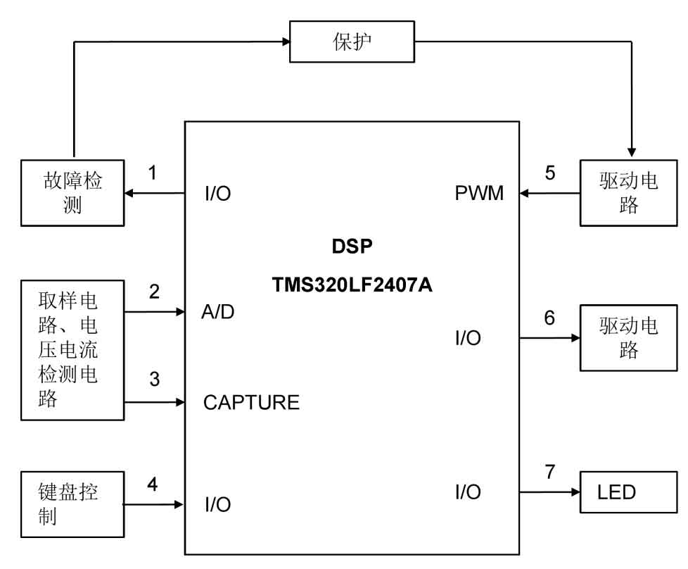
The sampling circuit in Figure 10 is the voltage and current detection circuit introduced in the previous chapter. They detect the current and voltage of the inverter output and the power grid respectively, with interfaces of A/D and CAPTURE. The fault detection module in the figure transfers the data to the protection module after collecting the circuit’s electricity information, and controls the PWM output pulse through the judgment of the protection module to control the circuit’s on/off. 6. The seven circuits are respectively the driving circuit for grid connected operation and the driving circuit for displaying the working status. This is a rough representation of the connection relationship and control range of a DSP chip in a control circuit.
3.3 System Control Program Flow
In the main program of the solar photovoltaic grid connected power generation system, there are no real-time judgment tasks involved, but mainly execute some established or conventional operating procedures of the solar photovoltaic grid connected power generation system. Tasks such as data sampling and analysis, real-time adjustment of the duty cycle of DC/DC conversion circuits, etc. are not within the scope of the main program design. The main program mainly executes programs such as system initialization, work jump interrupts, system shutdown and startup. In system initialization, the main task is to reset the data in some registers of the DSP chip, including restarting other modules that require resetting.