1. Introduction
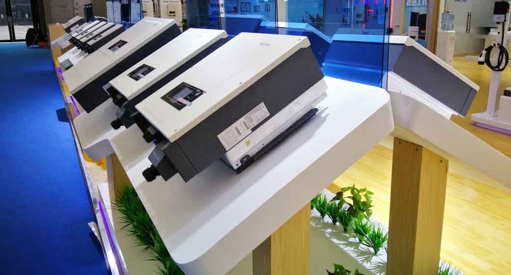
The rapid development of renewable energy systems has intensified the demand for efficient energy storage solutions. Among these, the energy storage inverter plays a pivotal role in managing power flow between photovoltaic (PV) systems, batteries, and the grid. This article focuses on the design, control, and implementation of a 10kW single-phase bidirectional energy storage inverter, emphasizing seamless mode transitions, advanced control algorithms, and hardware/software co-design.

2. Bidirectional AC/DC Converter Design
2.1 Topology and Operating Modes
The bidirectional AC/DC converter employs an H4 bridge topology (Figure 1), enabling both grid-tied rectification and inversion. Key operating modes include:
- Rectification Mode: Energy flows from the grid to the DC bus.
- Inversion Mode: Energy transfers from the DC bus to the grid.
The switching strategy uses unipolar sinusoidal pulse-width modulation (SPWM) to minimize losses and harmonic distortion.
2.2 Unified Control Strategy
To eliminate oscillations during mode transitions, a unified control framework integrates both rectification and inversion operations. The voltage outer loop and current inner loop are designed as follows:
Current Inner Loop (QPR Controller):GQPR(s)=kp+s2+2ωcs+ω022krωcs
where kp=1.6, kr=100, ωc=5rad/s, and ω0=314rad/s.
Voltage Outer Loop (PI Controller):GPI(s)=kp+ski
Parameters: kp=0.29, ki=0.021.
2.3 Simulation Results
Table 1 summarizes the system parameters. Simulations in PSIM validate the bidirectional converter’s performance:
| Parameter | Value |
|---|---|
| DC Bus Voltage (Vdc) | 400 V |
| Switching Frequency | 20 kHz |
| Filter Inductance (L) | 650 μH |
| DC Bus Capacitance (Cdc) | 1.88 mF |
- Rectification: Achieved 98.2% efficiency with THD < 3%.
- Inversion: Maintained grid synchronization with phase error < 1°.
3. Off-Grid Inverter Control
3.1 Dual-Loop Control Architecture
For off-grid operation, a voltage-current dual-loop control ensures stable output under nonlinear loads (e.g., rectifiers). The control structure includes:
- Voltage Outer Loop: Regulates output voltage.
- Current Inner Loop: Tracks reference current.
3.2 Advanced Control Algorithms
3.2.1 QPR + PI Composite Control
The quasi-proportional resonant (QPR) controller enhances harmonic suppression:GQPR(s)=kp+s2+2ωcs+ω022krωcs
3.2.2 LADRC + RC Composite Control
A linear active disturbance rejection controller (LADRC) combined with repetitive control (RC) improves dynamic response:LADRC: u=kpe+ki∫edt−s+ωob0zRC: GRC(s)=1−e−sTe−sT
Performance Comparison (Table 2):
| Control Method | THD (%) | Settling Time (ms) |
|---|---|---|
| Traditional PI | 4.8 | 25 |
| QPR + PI | 2.1 | 18 |
| LADRC + RC | 1.5 | 12 |
4. Seamless Grid-Connected/Off-Grid Transition
4.1 Control Strategy
The energy storage inverter employs a pre-synchronization algorithm to align voltage, frequency, and phase before mode switching. Key steps include:
- Grid Monitoring: Detect grid faults using voltage/frequency thresholds.
- Islanding Detection: Implement active frequency drift (AFD) for rapid isolation.
- Mode Transition: Smoothly switch between PQ (grid-tied) and VF (off-grid) control.
4.2 Transition Waveforms
- Grid → Off-Grid: Voltage dip < 5%, recovery within 20 ms.
- Off-Grid → Grid: Phase synchronization error < 0.5°.
5. Hardware and Software Design
5.1 System Architecture
The 10kW energy storage inverter comprises:
- Power Stage: H4 bridge, LC filters, and IGBT modules.
- Control Unit: TI TMS320F28035 DSP for real-time processing.
- Sampling Circuits: Isolated voltage/current sensors.
5.2 Key Component Selection
| Component | Specification |
|---|---|
| IGBT Module | 1200 V, 75 A |
| DC Bus Capacitor | 470 μF, 450 V |
| Grid Filter Inductor | 650 μH, 20 A |
5.3 Software Workflow
- Initialization: Configure PWM, ADCs, and communication interfaces.
- Main Loop: Execute control algorithms every 50 μs.
- Fault Handling: Overcurrent/overvoltage protection within 2 μs.
6. Experimental Validation
6.1 Prototype Testing
- Efficiency: 97.5% at full load (10 kW).
- THD: < 2.5% under nonlinear loads.
- Mode Transition: Completed within 1 grid cycle (20 ms).
6.2 Field Deployment
The energy storage inverter demonstrated reliable operation in a 50 kW PV-battery system, reducing peak grid demand by 40%.
7. Conclusion and Future Work
This study presents a comprehensive solution for 10kW single-phase energy storage inverters, achieving high efficiency, low distortion, and seamless mode transitions. Future work will explore:
- Wide-bandgap devices (SiC/GaN) for higher switching frequencies.
- AI-driven predictive maintenance.
- Scalability for three-phase systems.
The proposed strategies validate the energy storage inverter as a critical enabler for modern renewable energy systems, bridging gaps between generation, storage, and consumption.
