
The rapid transition toward renewable energy sources has profoundly reshaped modern power system architecture, with direct current (DC) microgrids emerging as a key enabling technology. DC microgrids offer higher energy conversion efficiency, simplified control structures, and more convenient integration of distributed generators and energy storage devices compared to their AC counterparts. Within the DC microgrid, the energy storage system serves as the critical component for suppressing power fluctuations and maintaining stable bus voltage operation. However, the persistent expansion in capacity and complexity of DC microgrids demands increasingly sophisticated control strategies for the constituent energy storage system. In particular, the hybrid energy storage system, which typically combines batteries with supercapacitors, leverages the complementary characteristics of energy-type storage and power-type storage to achieve superior system performance. Nevertheless, several challenges persist, including maintaining bus voltage stability under random disturbances, achieving rational power allocation among multiple battery units, and ensuring adequate protection for each energy storage device throughout prolonged operation. This thesis addresses these challenges through three interconnected contributions: an improved sliding mode active disturbance rejection control strategy for the bidirectional DC-DC converter on the energy storage side, an adaptive droop control method for state of charge (SOC) balancing across multiple battery banks, and a fuzzy second-order high-pass filtering approach for power distribution between batteries and supercapacitors.
Literature Review and Background
The evolution of DC microgrid technology has witnessed substantial progress globally. The United States pioneered early research through the SBI and SBN initiatives at Virginia Tech, followed by the FREEDM system architecture from North Carolina State University. European Union projects in the Netherlands and Denmark have demonstrated practical implementations of low-voltage DC microgrids incorporating renewable sources and electric vehicle charging infrastructure. Japan has contributed significant technical innovations in bipolar DC microgrid architectures with ±170V configurations. China has accelerated its DC microgrid research through various national key research programs, progressing from foundational studies to demonstration projects in Shenzhen, Xiamen, Suzhou, and Yancheng.
Two fundamental control levels exist in DC microgrids: system-level control and device-level control. System-level control focuses on mode switching, power allocation among energy storage devices, and secondary voltage regulation. Device-level control addresses the operational requirements of power electronic converters, including maximum power point tracking, charging/discharging management for energy storage devices, and DC bus voltage stabilization. Within these control hierarchies, the bidirectional DC-DC converter assumes a critical role as the power interface between storage elements and the DC bus.
Table 1 provides a comprehensive comparison of common energy storage technologies, illustrating why a single storage device cannot simultaneously meet the conflicting requirements of high energy density and high power density, nor provide both rapid dynamic response and extended cycle life.
| Storage Device | Energy Density (Wh/kg) | Power Density (W/kg) | Efficiency (%) | Annual Cost (RMB/kWh) | Lifetime (years) |
|---|---|---|---|---|---|
| Supercapacitor | 2~10 | 6000~17000 | 95~98 | 750 | 25~30 |
| Superconducting | <1 | 800~1200 | 90~92 | 1800 | 25~30 |
| Flywheel | 5~50 | 180~1800 | 88~92 | 500 | 25~30 |
| Lead-acid battery | 30~200 | 100~700 | 85~92 | 120 | 5~8 |
| Lithium-ion battery | 150~300 | 200~1500 | 90~95 | 1000 | 6~10 |
| Sodium-sulfur | 150~250 | 150~300 | 85~90 | 800 | 10~15 |
The combination of batteries (high energy density) with supercapacitors (high power density) constitutes the hybrid energy storage system architecture that balances energy capacity with dynamic power response. However, obtaining the maximum benefit from such a hybrid energy storage system requires careful attention to the power allocation strategy, where low-frequency fluctuations are directed toward the battery and high-frequency components toward the supercapacitor.
System Modeling and Configuration
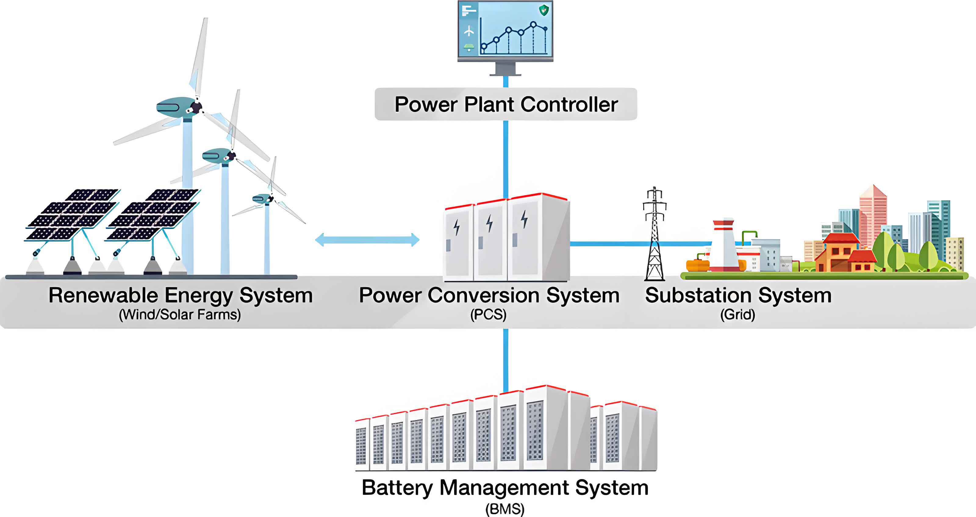
The studied system, as depicted in the figure above, presents the topology of an isolated photovoltaic DC microgrid with a hybrid energy storage system. The photovoltaic generation unit supplies power to the DC bus through a Boost converter. The hybrid energy storage system, comprising two battery banks and one supercapacitor bank, connects to the DC bus through three independent bidirectional DC-DC converters. The active topology has been selected for the hybrid energy storage system because it enables precise independent control of both the battery and supercapacitor charging/discharging processes while providing maximum control flexibility. This architecture offers superior bus voltage regulation, enhanced battery protection, and improved overall system reliability despite the additional cost of an extra converter.
Photovoltaic Cell Modeling
The photovoltaic cell operates on the principle of the photovoltaic effect, where light energy directly converts into electrical energy within a semiconductor PN junction. The single-diode equivalent circuit model effectively characterizes the photovoltaic cell behavior. The output current expression is given by:
$$I_{PV} = I_{ph} – I_0 \left[ \exp\left(\frac{q(U_{PV} + I_{PV}R_{se})}{AKT}\right) – 1\right] – \frac{U_{PV} + I_{PV}R_{se}}{R_{pa}}$$
In this equation, \(I_{ph}\) represents the photogenerated current, \(I_0\) is the reverse saturation current, \(q\) is the electron charge, \(A\) is the diode ideality factor, \(K\) is the Boltzmann constant, and \(T\) is the cell temperature. \(R_{se}\) and \(R_{pa}\) denote the series and parallel resistances, respectively. For standard conditions (\(S_{ref} = 1000\,\text{W/m}^2\), \(T_{ref} = 25^\circ C\)), the model can be simplified and then corrected for variations in irradiance and temperature using:
$$
\begin{aligned}
I’_{sc} &= I_{sc}\frac{S}{S_{ref}}[1 + a(T – T_{ref})] \\
U’_{oc} &= U_{oc}[1 – c(T – T_{ref})]\ln\left[e + b\left(\frac{S}{S_{ref}} – 1\right)\right]
\end{aligned}
$$
where \(a = 0.0025/^\circ C\), \(b = 0.5\,\text{m}^2/W\), and \(c = 0.00288/^\circ C\) are compensation coefficients. The output characteristics are strongly nonlinear, with temperature predominantly affecting the open-circuit voltage and maximum power point, while irradiance primarily governs the short-circuit current behavior.
Battery and Supercapacitor Models
The battery is modeled using the Thevenin equivalent circuit, comprising an ideal voltage source \(E_t\), internal resistance \(r_t\), polarization capacitance \(C_s\), and overvoltage resistance \(R_s\). The terminal voltage is expressed as:
$$U_t = E_t – I_t r_t – U_s$$
The state of charge (SOC) estimation employs the Coulomb counting (ampere-hour integration) method:
$$SOC(t) = SOC(0) – \frac{\int I_{bat}\, dt}{C_{bat}}$$
where \(C_{bat}\) is the battery rated capacity. The supercapacitor model consists of a capacitance \(C\) in series with an equivalent series resistance \(R_{es}\) and a parallel leakage resistance \(R_{ep}\). Its SOC is determined from the terminal voltage relationship:
$$SOC_{sc} = \frac{Q_t}{Q_N} = \frac{U_{oc} – U_{\min}}{U_{\max} – U_{\min}}$$
The active topology with each storage element connected through its own bidirectional DC-DC converter ensures optimal controllability for the subsequent coordinated control strategies.
Improved Sliding Mode Active Disturbance Rejection Control for the Bidirectional DC-DC Converter
The bidirectional DC-DC converter serves as the power interface between the energy storage device and the DC bus. Its control performance directly determines the bus voltage quality and overall system stability. This chapter develops an improved sliding mode active disturbance rejection control (SMADRC) strategy with a cascaded architecture to enhance the disturbance rejection capability of the converter under random perturbations.
Mathematical Model of the Bidirectional DC-DC Converter
The non-isolated bidirectional Buck/Boost converter operates in two modes. When the power flows from the storage side to the bus side, the converter operates in Boost mode; conversely, in Buck mode, energy flows from the bus to the storage side. Using the state-space averaging method with the inductor current \(I_L\) and bus voltage \(U_{dc}\) as state variables, the averaged equations for Boost mode are:
$$
\begin{aligned}
L\frac{dI_L}{dt} &= U_b – (1-D)U_{dc} \\
C\frac{dU_{dc}}{dt} &= (1-D)I_L – I_{dc}
\end{aligned}
$$
For Buck mode, the state equations become:
$$
\begin{aligned}
L\frac{dI_L}{dt} &= D U_{dc} – U_b \\
C\frac{dU_{dc}}{dt} &= I_L – I_{dc}
\end{aligned}
$$
Both modes indicate that the duty cycle \(D\) provides the control handle for regulating both the inductor current and the bus voltage, confirming the feasibility of a cascaded voltage-current control architecture.
Voltage Outer Loop Design Using Novel Extended State Observer
The voltage outer loop must maintain robust bus voltage tracking under various uncertainties. The analysis begins by approximating the bus voltage dynamics as a first-order system:
$$\dot{k} = f(t) + b_0 u$$
where \(k = U_{dc}\), \(u = I_{L\_ref}\), and \(f(t)\) represents the total disturbance including external disturbances and internal uncertainties. The state variables are defined as \(l_1 = k\) and \(l_2 = f(t)\). The traditional linear extended state observer (LESO) estimates the system states using:
$$
\begin{aligned}
\dot{v}_1 &= v_2 + b_0 u + \beta_1(U_{dc} – v_1) \\
\dot{v}_2 &= \beta_2(U_{dc} – v_1)
\end{aligned}
$$
The bandwidth parameter \(\omega_0\) configures the observer gains as \(\beta_1 = 2\omega_0\) and \(\beta_2 = \omega_0^2\). In the improved LESO proposed in this work, both the proportional and integral terms of the observation error jointly estimate the total disturbance:
$$
\begin{aligned}
\dot{v}_1 &= v_2 + b_0 u \\
\dot{v}_2 &= \beta_1 e + \beta_2 \int e \, dt
\end{aligned}
$$
where \(e = U_{dc} – v_1\) is the observation error. The error dynamics follow:
$$
\begin{aligned}
\dot{e}_1 &= e_2 \\
\dot{e}_2 &= -\beta_1 e – \beta_2 e_1 + \dot{f}
\end{aligned}
$$
Pole placement yields the same gain structure, but the transfer function analysis reveals significant improvements. The disturbance estimation transfer function for the improved LESO is:
$$\frac{v_2}{f} = \frac{2\omega_0 s + \omega_0^2}{s^2 + 2\omega_0 s + \omega_0^2}$$
Compared with the traditional observer, the improved LESO exhibits flatter magnitude attenuation across the mid-to-high frequency bands, enabling precise tracking of faster disturbance signals. The phase lag is reduced across the entire frequency spectrum, increasing the phase margin and accelerating the system dynamic response. The Lyapunov function \(V_1 = e_1^2/2 + e_2^2/(2\beta_1)\) guarantees practical convergence of the error system when the disturbance derivative is bounded.
Sliding Mode Error Feedback Control Law
To enhance robustness further, a sliding mode control law replaces the conventional linear error feedback. The fast power reaching law is expressed as:
$$\dot{s} = -k_1 s – k_2 |s|^{\gamma} \text{sign}(s)$$
with \(k_1 > 0\), \(k_2 > 0\), and \(0 < \gamma < 1\) (typically \(\gamma = 0.5\)). The integral sliding surface is constructed as:
$$s_1 = e_u + k_i \int e_u \, d\tau$$
where \(e_u = U_{dc\_ref} – v_1\). The resulting control law becomes:
$$u = \frac{k_1 s_1 + k_2 |s_1|^{0.5} \text{sign}(s_1) + k_i e_u – v_2}{b_0}$$
To eliminate chattering inherent to discontinuous sign functions, a continuous sigmoid function replaces the switching function:
$$\text{sigmoid}(s) = \frac{2}{1 + e^{-\lambda s}} – 1$$
Stability verification using \(V_2 = s_1^2/2\) demonstrates that \(V_2 < 0\) for \(s_1 \neq 0\), confirming finite-time convergence of the sliding surface.
Current Inner Loop Design Using Improved Super-Twisting Sliding Mode Control
The current inner loop provides fast tracking of the inductor current reference. The conventional super-twisting algorithm:
$$
\begin{aligned}
\dot{s} &= -w_1 |s|^{0.5} \text{sign}(s) + v \\
\dot{v} &= -w_2 \text{sign}(s)
\end{aligned}
$$
is modified by replacing the sign function with the smooth sigmoid function, yielding the improved super-twisting sliding mode control (STSMC). Considering the Boost-mode inductor current dynamics, the control law computes the duty cycle as:
$$D = \frac{L}{U_{dc}}\left[\alpha_1 |s_2|^{0.5} \text{sigmoid}(s_2) + \alpha_2 \int \text{sigmoid}(s_2)\, dt\right]$$
with the sliding surface \(s_2 = I_{L\_ref} – I_L\). Lyapunov analysis using the state vector \(\boldsymbol{\zeta}^T = [|s_2|^{0.5}\text{sigmoid}(s_2), v]\) establishes the Hurwitz property of the linearized system matrix, proving the global asymptotic stability of the closed-loop error system in the presence of bounded external disturbances.
Simulation Validation
Table 2 summarizes the controller parameters used in the simulations.
| Control Strategy | Voltage Loop Parameters | Current Loop Parameters |
|---|---|---|
| LADRC+STSMC | \(\omega_0=900\), \(b_0=1000\), \(\omega_c=200\) | \(\alpha_1=8\), \(\alpha_2=300\), \(\lambda_2=1\) |
| SMADRC+STSMC | \(\omega_0=900\), \(b_0=1000\), \(k_1=85\), \(k_2=190\), \(\lambda_1=1\), \(k_i=1\) | \(\alpha_1=8\), \(\alpha_2=300\), \(\lambda_2=1\) |
Table 3 lists the main circuit parameters.
| Parameter | Value |
|---|---|
| DC bus voltage reference / V | 400 |
| Storage-side rated voltage / V | 200 |
| Storage-side inductance / H | 0.005 |
| Filter capacitance / F | 0.001 |
| Switching frequency / kHz | 20 |
Simulation results under system startup demonstrate that the proposed SMADRC+STSMC strategy achieves a settling time of approximately 12 ms, whereas the conventional LADRC+STSMC requires 36 ms, confirming faster voltage tracking performance. During load disturbance tests where the load power stepped between 3 kW and 7 kW, the voltage overshoot decreased from 3.81 V to 1.58 V and the recovery time reduced from 20.5 ms to 3.7 ms as compiled in Table 4.
| Scenario | Strategy | Deviation (V) | Recovery Time (ms) |
|---|---|---|---|
| Load drop (7→3 kW) | LADRC+STSMC | 3.81 | 20.5 |
| Load drop (7→3 kW) | SMADRC+STSMC | 1.58 | 3.7 |
| Load rise (3→7 kW) | LADRC+STSMC | 4.05 | 22.5 |
| Load rise (3→7 kW) | SMADRC+STSMC | 1.53 | 3.3 |
| Irradiance drop (1000→500 W/m²) | LADRC+STSMC | 2.97 | 18.1 |
| Irradiance drop (1000→500 W/m²) | SMADRC+STSMC | 2.28 | 6.5 |
| Irradiance rise (500→1200 W/m²) | LADRC+STSMC | 3.75 | 19.6 |
| Irradiance rise (500→1200 W/m²) | SMADRC+STSMC | 2.78 | 3.1 |
These results uniformly confirm that the proposed SMADRC+STSMC strategy significantly reduces voltage deviations and accelerates transient recovery, thereby enhancing the bus voltage stability of the energy storage system under both load and source perturbations.
Improved Adaptive Droop Control for SOC Balancing of Multiple Battery Banks
When multiple battery storage units operate in parallel in the DC microgrid, differences in initial SOC and rated capacity can lead to overcharging or overdischarging of individual units if conventional fixed-droop control is used. This chapter proposes an improved adaptive droop control strategy based on battery SOC to achieve balanced and coordinated operation.
Conventional Droop Control and Its Limitations
The I-U droop control expression is:
$$U_{oi} = U_{dc\_ref} – R_i I_{oi}$$
where \(U_{oi}\) and \(I_{oi}\) are the converter output voltage and current, and \(R_i\) is the droop coefficient. Two parallel-connected converters have the relationship:
$$\frac{I_{oi}}{I_{oj}} = \frac{R_j + r_j}{R_i + r_i}$$
presuming the load-sharing accuracy is primarily governed by droop coefficients when these dominate over line resistances. The conventional droop approach introduces an inherent trade-off: larger droop gains improve current sharing accuracy but increase voltage deviation. This compromise, combined with the absence of SOC awareness, constitutes the fundamental drawback of conventional droop control implementing an energy storage system.
Improved Adaptive Droop Control Strategy
The SOC estimation relies on the ampere-hour integral method stated earlier. The SOC balancing mechanism requires the droop coefficient of each converter to respond adaptively to the SOC state of its associated battery. Using the arctangent function establishes a bounded nonlinear mapping between the SOC deviation \(\Delta SOC_i = SOC_i – SOC_{av}\) and the adaptive droop coefficient. During discharge, the droop coefficient is:
$$R_i = R_0 + \frac{R_{\max} – R_0}{\pi/2} \arctan\left(m_i \Delta SOC_i\right)$$
During charging, the droop relationship becomes:
$$R_i = R_0 + \frac{R_{\max} – R_0}{\pi/2} \arctan\left(-m_i \Delta SOC_i\right)$$
This structure limits the droop coefficient strictly within [\(R_{\min}\), \(R_{\max}\)], preventing the unstable condition of an unbounded droop parameter. To accelerate the SOC balancing process without compromising initial stability, a variable acceleration factor is introduced:
$$m_i = m_0 + \frac{M}{\Delta SOC_i^2 + a}$$
with \(0 < a < 1\) and \(M\) a proportional coefficient. Table 5 presents the design parameters for the adaptive droop controller.
| Parameter | Symbol | Value |
|---|---|---|
| Initial droop coefficient | \(R_0\) | 1 |
| Maximum droop coefficient | \(R_{\max}\) | 3 |
| Minimum droop coefficient | \(R_{\min}\) | 0.1 |
| Base acceleration coefficient | \(m_0\) | 200 |
| Acceleration adjustment | \(a\) | 0.01 |
| Proportional coefficient | \(M\) | 8 |
Considering battery capacity disparity, the rated capacity is incorporated into the droop coefficient expression. For the discharge process, the capacity-corrected droop becomes:
$$R_i = \frac{C_{\max}}{C_i} R_0 + \frac{C_{\max}}{C_i} \frac{R_{\max} – R_0}{\pi/2} \arctan\left(\left(m_0 + \frac{M}{\Delta SOC_i^2 + a}\right)\Delta SOC_i\right)$$
Similar correction applies for the charging direction, ensuring that rated capacities of the battery banks are respected during power sharing, thus keeping the SOC change rates of different-capacity batteries proportional.
Secondary Bus Voltage Control
The droop action inevitably introduces voltage deviations, and a secondary voltage control layer compensates for this effect. The compensation signal \(u_i\) is generated by a PI regulator acting on the voltage deviation:
$$u_i = K_{Pi} e_{Li} + K_{Ii} \int e_{Li} \, dt + U_{xi}$$
where \(e_{Li}\) is the locally computed voltage error from the mean virtual voltage drop \(U_{xi}\). Simulation results under varying load and irradiance conditions confirm that the bus voltage is restored exactly to its reference after the secondary controller activation, while the two batteries reach SOC equality at approximately 14.6 s. Table 6 summarizes the observed SOC convergence times under different initial SOC conditions.
| Operating Mode | Initial SOC\(_1\) (%) | Initial SOC\(_2\) (%) | Balancing Time (s) |
|---|---|---|---|
| Discharge | 53 | 50 | ~14.6 |
| Charge/Discharge cycling | 53 | 50 | ~12.1 |
Fuzzy Second-Order High-Pass Filtering Power Allocation for the Hybrid Energy Storage System
After establishing the voltage converter control and the SOC balancing among battery banks, the overall power allocation between the battery bank and the supercapacitor must be addressed for the hybrid energy storage system. The power balance equation governing the DC microgrid is:
$$C_{dc} U_{dc} \frac{dU_{dc}}{dt} = P_{PV} + P_b + P_{sc} – P_{load}$$
The hybrid energy storage system output current components must satisfy the instantaneous current balance:
$$I_{ob1} + I_{ob2} + I_{osc} = I_{oPV} – I_{load} = I_{ref}$$
The high-frequency power components are assigned to the supercapacitor, while the low-frequency components are directed to the batteries.
Limitations of First-Order High-Pass Filter
The first-order high-pass filter (HPF) transfer function is:
$$H(s) = \frac{T_h s}{1 + T_h s}$$
An unavoidable integral action accumulates in the supercapacitor response. The final-value theorem demonstrates that:
$$\int_0^{\infty} I_{sc}(t)\, dt = \lim_{s\to 0} \frac{T_h s}{1 + T_h s} I_{ref}(s) = T_h Z$$
where \(Z = \lim_{t\to\infty} I_{ref}(t)\). This integral accumulation proportional to the reference current final value and the time constant \(T_h\) leads to the gradual drift of the supercapacitor SOC, which is particularly problematic during sustained power mismatches.
Second-Order High-Pass Filter Allocation
The second-order high-pass filter eliminates this accumulation. The revised current allocation strategy is:
$$
\begin{aligned}
I_{sc\_ref}(s) &= \left(\frac{T_h s}{1 + T_h s}\right)^2 I_{ref}(s) \\
I_{b\_ref}(s) &= \left(1 – \left(\frac{T_h s}{1 + T_h s}\right)^2\right) I_{ref}(s) = \frac{1 + 2T_h s}{(1 + T_h s)^2} I_{ref}(s)
\end{aligned}
$$
The integral of the supercapacitor current now evaluates to:
$$\int_0^{\infty} I_{sc}(t)\, dt = \lim_{s\to 0} \left(\frac{T_h s}{1 + T_h s}\right)^2 I_{ref}(s) = 0$$
Thus, no capacitance accumulation occurs in the long-term response of the supercapacitor when subjected to step changes in the reference current. The supercapacitor naturally returns to its initial SOC after each transient event, preventing SOC saturation and loss of regulation capability. The Bode analysis further confirms steeper roll-off characteristics compared to the first-order case, improving frequency selectivity. Table 7 compares the step-response properties of the two filters.
| Criterion | First-order HPF | Second-order HPF |
|---|---|---|
| Integral accumulation | \(T_h Z\) | 0 |
| Roll-off rate | 20 dB/decade | 40 dB/decade |
| Supercapacitor SOC recovery | Not achieved | Achieved |
| Real-time SOC protection | Not provided | Provided via fuzzy control |
Fuzzy Adaptive Adjustment of the Filtering Time Constant
The filtering time constant \(T_h\) determines which frequency components are assigned to the supercapacitor. A larger \(T_h\) broadens the frequency range assigned to the supercapacitor; conversely, a smaller \(T_h\) narrows it. To protect the supercapacitor from overcharging or overdischarging, a fuzzy controller dynamically adjusts \(T_h\) based on the real-time supercapacitor SOC. The input variable is \(SOC_{sc}\) with domain [0, 100], and the output is \(T_h\) with domain [0.2, 0.4]. Five linguistic labels, S1 through S5, and T1 through T5, are defined, respectively. The fuzzy rules are shown in Table 8.
| \(SOC_{sc}\) | \(T_h\) during discharge | \(T_h\) during charge |
|---|---|---|
| S1 (very low) | T1 (minimum) | T5 (maximum) |
| S2 (low) | T2 | T4 |
| S3 (medium) | T3 | T3 |
| S4 (high) | T4 | T2 |
| S5 (very high) | T5 (maximum) | T1 (minimum) |
The output membership functions utilize triangular shapes, while the inputs use a combination of Gaussian and triangular functions to enable smooth transitions across the SOC range. This fuzzy adaptation mechanism ensures that the supercapacitor gradually reduces its participation when its SOC approaches a critical limit, thereby maintaining the SOC in its safe operating region.
Coordinated Control Architecture
The complete coordinated control strategy integrates the three layers. At the innermost layer, the SMADRC-based voltage outer loop and STSMC-based current inner loop stabilize the DC bus voltage and provide fast current tracking. The intermediate layer implements the SOC-balancing adaptive droop control for multiple battery banks, together with the secondary voltage control loop. The outermost layer applies the fuzzy second-order high-pass filtering to split the total power reference between the battery bank and the supercapacitor. This multilayer structure enables unified energy management for the entire hybrid energy storage system.
Simulation Results for Coordinated Control
The overall system was simulated under a complex, time-varying profile where the photovoltaic power and load demand both experienced repeated step changes and the irradiation level fluctuated. The photovoltaic power ranged between approximately 7.3 kW under reduced irradiation and 16.8 kW under enhanced irradiation, while the load power stepped among values in the 10–21 kW range. Several key findings emerged from the simulation results.
The DC bus voltage remained tightly regulated at the 400 V reference throughout all transients, with deviations typically below 1% and rapid recovery after each disturbance. The secondary voltage controller compensated the voltage drop introduced by the droop mechanism, restoring the bus voltage to a precise no-difference state under steady-state conditions. The dynamic deviations caused by sudden load or source switching were effectively suppressed by the SMADRC-tuned voltage loop, confirming the strong disturbance rejection capability of the proposed energy storage system controls.
The two battery banks, with initial SOC values of 53% and 50% respectively, converged to a common SOC within approximately 15 seconds, as recorded in Table 9. The improved adaptive droop control algorithm adjusted the droop coefficients in real time according to the instantaneous SOC differences, causing the higher-SOC battery to deliver more power during discharge and absorb less during charge. After convergence, the droop coefficients became inversely proportional to the rated capacities of the battery banks, ensuring that the two batteries witnessed proportional current sharing and matched SOC dynamics.
The supercapacitor successfully intercepted the high-frequency components of the unbalanced power, effectively protecting the battery from excessive transient stress. The fuzzy second-order high-pass filter prevented SOC accumulation in the supercapacitor during sustained power mismatch. The supercapacitor SOC exhibited a self-recovery behavior, returning to its initial level after each transient event, demonstrating that the coordinated control strategy protected the supercapacitor from overcharging or overdischarging scenarios.
| Control Objective | Performance Indicator | Observed Result |
|---|---|---|
| Bus voltage regulation | Maximum deviation | <1% of reference |
| Voltage recovery | Settling time | <10 ms |
| Battery SOC balancing | Balancing time | ~15 s |
| Supercapacitor SOC protection | SOC deviation from initial | ~0% after transients |
| Current-sharing accuracy | Steady-state error | <2% |
The simulation outcomes confirmed that the coordinated energy storage system control strategy successfully integrated the voltage stabilization, SOC balancing, and power-splitting functions into a unified framework, demonstrating robust performance under realistic operating scenarios of renewable energy variability and load switching.
Conclusions and Future Work
This thesis has systematically investigated the coordinated control strategies for a hybrid energy storage system within a DC microgrid. Three principal contributions have been established. First, the novel sliding mode active disturbance rejection control with an improved extended state observer augmented by proportional-integral observation errors and a fast power reaching law has demonstrated superior bus voltage regulation under both load and source perturbations when compared with the conventional linear active disturbance rejection control. Second, the improved adaptive droop control constructed with an arctangent function introduced a bounded nonlinear droop coefficient that balances the conflicting requirements for reasonable power sharing and bus voltage precision, further enhanced by the variable acceleration factor and the secondary voltage control strategy. Third, the fuzzy second-order high-pass filtering allocation method has effectively eliminated the integral accumulation effect that degrades the performance of the supercapacitor in conventional first-order filter implementations, while the fuzzy controller guarantees adaptive supercapacitor SOC protection.
The integration of these three layers into a unified coordinated control framework enables the hybrid energy storage system to simultaneously achieve fast bus voltage restoration, rapid SOC equalization among multiple battery banks, and rational frequency-based power splitting between battery and supercapacitor. As a result, the overall operational stability and storage equipment lifetime of the DC microgrid are substantially improved.
Several directions merit future investigation. In particular, the study of the grid-connected operating mode and the seamless transition between grid-connected and islanded modes of the DC microgrid would broaden the applicability of the proposed strategies. In addition, the construction of a physical experimental platform capable of validating the theoretical findings under real hardware constraints would considerably strengthen the practical relevance of this research. Finally, the extension of the coordinated control methodology to more complex multi-microgrid structures with multiple interconnected energy storage systems warrants dedicated attention in subsequent work.