
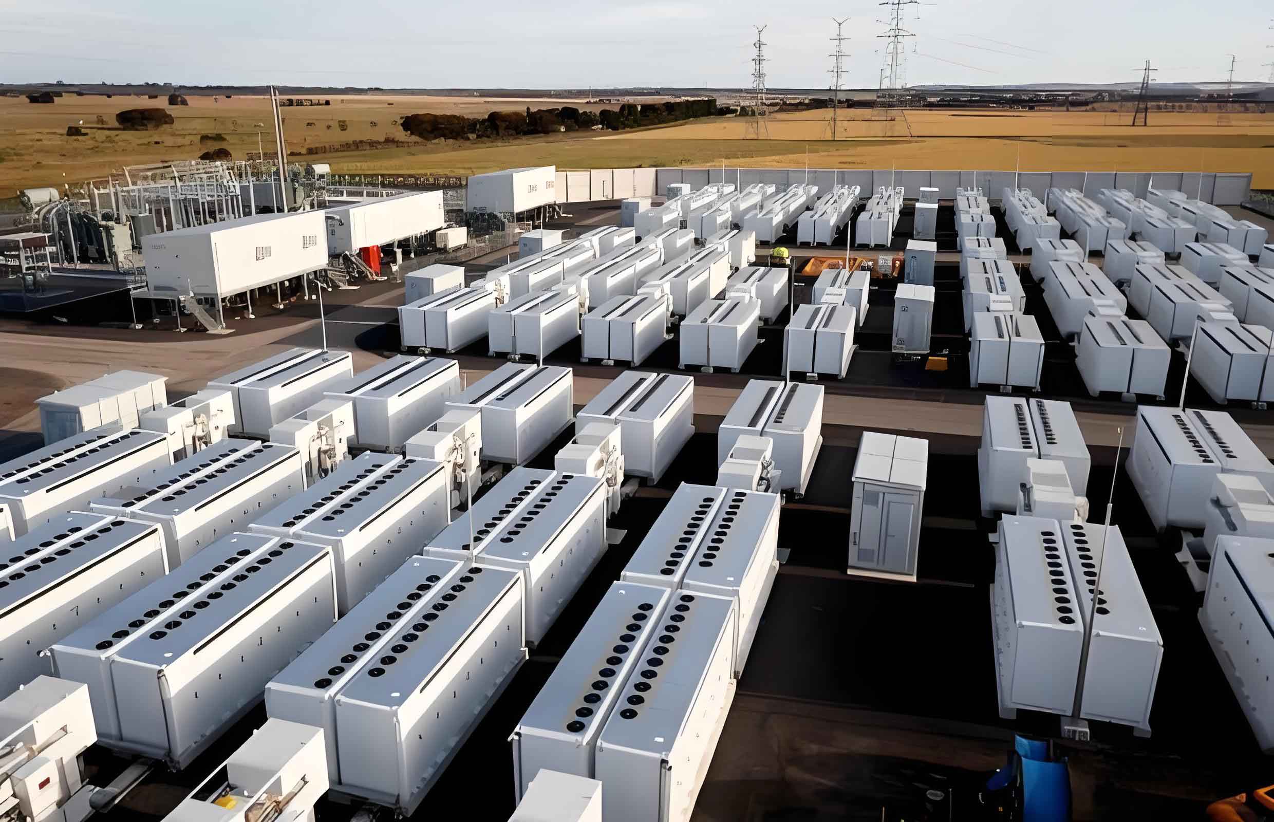
In modern power systems, the integration of renewable energy sources such as solar and wind has introduced challenges due to their inherent volatility, randomness, and anti-peak characteristics. To mitigate these issues, large-scale energy storage systems have become essential. Among these, battery energy storage systems (BESS) offer a promising solution by providing stability, frequency regulation, and power buffering. The modular multilevel converter (MMC) based battery energy storage system (MMC-BESS) has gained significant attention for its modularity, scalability, and ability to handle high-voltage and high-power applications. However, traditional MMC-BESS topologies, where every submodule is equipped with a battery, can be costly and inefficient when full energy storage capacity is not required. This has led to the development of partially integrated battery energy storage systems within MMC (MMC-PBESS), which reduce costs by integrating batteries only in a subset of submodules, such as in the lower bridge arms. In this article, I explore a control method for an MMC-PBESS topology where batteries are integrated solely into the lower bridge arms. I present a mathematical model, derive an equivalent circuit, propose a capacitor voltage balancing strategy, and introduce a decoupled control strategy for the upper and lower bridge arms. Additionally, I analyze the operational boundaries and validate the approach through simulation studies.
The motivation behind MMC-PBESS stems from the need to balance cost-effectiveness with functional requirements in grid applications. A battery energy storage system typically comprises battery packs, battery management systems, energy management systems, power converters, and other electrical components. While reducing battery capacity per submodule can lower costs, the relationship is not linear, as ancillary systems like battery management remain necessary. Therefore, partially integrating batteries—for instance, in half of the submodules—can significantly cut expenses while still meeting energy storage needs for services like inertia support, primary frequency regulation, and black-start capabilities. This topology transforms the MMC into a three-port network, facilitating power exchange among the DC side, AC side, and the energy storage port. The key challenge lies in managing the asymmetric nature of the upper and lower bridge arms, which requires tailored control strategies to maintain system stability and performance.
To begin, I establish a mathematical model for the MMC-PBESS with lower-arm integrated batteries. Consider a three-phase MMC-PBESS where each phase consists of an upper bridge arm with N capacitor submodules (SMCs) and a lower bridge arm with N battery submodules (SMBs), all connected in series with an arm inductor \(L_a\). The DC bus voltage is denoted as \(U_{dc}\), the battery voltage per submodule as \(U_B\), and the AC grid voltage as \(u_{gj}\) for phase \(j = a, b, c\). The submodules are half-bridge types, with capacitors \(C\) in SMCs and a parallel capacitor \(C_0\) in SMBs to buffer the battery. The system is connected to the AC grid via inductors \(L_g\). Assuming ideal conditions, the power balance among the DC port, AC port, and battery energy storage system port is given by \(P_{dc} – P_{ac} = P_{bat}\), where directions are defined as positive into the converter.
For the DC side analysis, the DC bus current \(I_{dc}\) is equally distributed among the three phases:
$$ i_{dcj} = \frac{I_{dc}}{3} $$
where \(i_{dcj}\) is the DC component of the upper and lower arm currents in phase \(j\). Applying Kirchhoff’s voltage law to the DC loop yields:
$$ 2L_a \frac{di_{dcj}}{dt} = U_{dc} – (u_{pj} + u_{nj}) $$
Here, \(u_{pj}\) and \(u_{nj}\) represent the total equivalent voltages of the upper and lower arm submodules in phase \(j\), respectively. Additionally, the battery voltage relates to the DC voltage as \(U_{dc} = N U_B\), assuming uniform battery submodules.
On the AC side, the relationship between arm voltages and the grid voltage is approximated as:
$$ u_{gj} \approx \frac{1}{2}(u_{nj} – u_{pj}) $$
The AC grid current \(i_j\) is the difference between the upper and lower arm currents:
$$ i_j = i_{pj} – i_{nj} $$
Due to the asymmetry from battery integration, the AC current is not equally split between the arms. Let \(\eta\) (where \(0 < \eta < 1\)) be the fraction of the AC current carried by the upper arm. Thus, the AC components of the arm currents are:
$$ i_{p,ac,j} = \eta i_j $$
$$ i_{n,ac,j} = -(1 – \eta) i_j $$
Hence, the total arm currents are:
$$ i_{pj} = i_{dcj} + i_{p,ac,j} $$
$$ i_{nj} = i_{dcj} + i_{n,ac,j} $$
Taking phase A as an example, the Kirchhoff voltage equations for the upper and lower arm loops are:
$$ u_{ga} = -u_{pa} – L_g \frac{di_a}{dt} – L_a \frac{di_{pa}}{dt} = -u_{pa} – \left( \frac{1}{\eta} L_g + L_a \right) \frac{di_{pa}}{dt} $$
$$ u_{ga} = u_{na} – L_g \frac{di_a}{dt} + L_a \frac{di_{na}}{dt} = u_{na} + \left( \frac{1}{1 – \eta} L_g + L_a \right) \frac{di_{na}}{dt} $$
These equations form the AC side model, with equivalent circuits shown in the analysis. The parameter \(\eta\) is crucial as it determines the power distribution between the arms. To maintain capacitor voltage balance in the upper arm, a specific condition must be met: the DC power component in the upper arm should equal its AC power component. For phase A, ignoring higher-order harmonics, the upper arm current and voltage can be expressed as:
$$ i_{pa} = \frac{I_{dc}}{3} + \eta I_m \cos(\omega t) $$
$$ u_{pa} = \frac{U_{dc}}{2} – U_m \cos(\omega t) $$
where \(I_m\) and \(U_m\) are the amplitudes of the AC grid current and voltage, respectively, and \(\omega\) is the grid angular frequency. The DC power component in the upper arm is derived from the product of the DC terms, leading to the balance condition:
$$ P_{dcp} = P_{acp} $$
Here, \(P_{dcp}\) and \(P_{acp}\) are the DC and AC powers handled by the upper arms of all phases. This condition ensures that the capacitor voltages in the upper arm remain stable over time.
To achieve this balance, I propose a capacitor voltage balancing strategy consisting of two levels: arm-averaged voltage control and individual submodule voltage control. For arm-averaged voltage control, define the average capacitor voltage in the upper arm of phase \(j\) as:
$$ u_{j,p,av} = \frac{1}{N} \sum_{i=1}^{N} u_{jpi} $$
where \(u_{jpi}\) is the capacitor voltage of the \(i\)-th SMC in the upper arm. A PI controller adjusts the DC current reference based on the error between \(u_{j,p,av}\) and the setpoint \(u_{c,ref}\). If the average voltage is below the setpoint, the DC current reference increases, charging the capacitors and raising the voltage. This control maintains the overall arm voltage at the desired level.
For individual submodule voltage balancing, each SMC’s capacitor voltage is regulated by modifying its modulation wave. When the arm current is positive, if a capacitor voltage is below \(u_{c,ref}\), its on-time is extended by increasing its modulation wave; if above, the on-time is reduced. The adjustment is reversed for negative arm currents. This method ensures that all capacitors within an arm stay balanced despite parameter variations or uneven switching.
The core of my control approach is the decoupled control strategy for the upper and lower bridge arms, which I term “separate control.” Unlike traditional MMC control that couples the arms, this strategy independently regulates the upper and lower arm currents to leverage the battery energy storage system’s functionality. The DC side control is conventional, deriving the DC current reference from the DC power setpoint \(P_{dc}\). For the AC side, I apply dq-transformation and dual-loop control. The outer loop sets the power reference, and the inner loop controls the arm currents with grid voltage feedforward and dq-decoupling. The equivalent inductances differ: \(L_g/\eta + L_a\) for the upper arm and \(L_g/(1-\eta) + L_a\) for the lower arm.
Let \(I_D\) be the d-axis reference for the total AC grid current, calculated from the AC power reference \(P_{ac}\) and grid voltage amplitude \(U_m\):
$$ I_D = \frac{2P_{ac}}{3U_m} $$
Assuming unity power factor, the d-axis references for the upper and lower arm currents, \(I_{Dp}\) and \(I_{Dn}\), must satisfy:
$$ I_{Dp} – I_{Dn} = I_D $$
To maintain upper arm capacitor voltage balance, \(I_{Dp}\) is fixed based on the power balance condition. Considering the modulation index \(m \approx 1\) (where \(m = 2U_m/U_{dc}\)), the upper arm modulation wave’s AC component is approximately half of the DC component. For half-bridge submodules to operate within the linear modulation range, the lower arm’s AC modulation component must not exceed that of the upper arm, imposing the constraint:
$$ |I_{Dn}| \leq |I_{Dp}| $$
Now, analyze the operational boundaries by defining the ratio of AC to DC power as \(k = P_{ac}/P_{dc}\), with \(P_{dc} \geq 0\) (i.e., power flowing into the converter from the DC side). The upper arm handles half of the DC power, \(P_{dcp} = P_{dc}/2\), and to satisfy capacitor balance, \(P_{acp} = P_{dcp}\). Hence, the AC powers are distributed as:
$$ P_{acp} = \frac{1}{2k} P_{ac} $$
$$ P_{acn} = \left(1 – \frac{1}{2k}\right) P_{ac} $$
From these, the current references are derived:
$$ I_{Dp} = \frac{I_D}{2k} $$
$$ I_{Dn} = -\frac{(2k – 1)I_D}{2k} $$
The permissible range for \(k\) depends on the constraint \(|I_{Dn}| \leq |I_{Dp}|\). I summarize the operational modes in the table below:
| Power Ratio \(k\) | Condition on \(k\) | Upper Arm Current \(I_{Dp}\) | Lower Arm Current \(I_{Dn}\) | Battery Energy Storage System Role | Feasibility with Half-Bridge Submodules |
|---|---|---|---|---|---|
| \(k < 0\) | \(P_{ac} < 0\), both sides input power | \(I_D/(2k) > 0\) | \(-(1-2k)I_D/(2k) > 0\) | Battery charging from both AC and DC | Not feasible (constraint violated) |
| \(0 < k < 0.5\) | \(0 < P_{ac} < P_{dc}/2\) | \(I_D/(2k) > I_D > 0\) | \(-(2k-1)I_D/(2k) > 0\) | Battery absorbs excess AC power from upper arm | Feasible |
| \(0.5 \leq k < 1\) | \(P_{dc}/2 \leq P_{ac} < P_{dc}\) | \(0 < I_D/(2k) \leq I_D\) | \(-(2k-1)I_D/(2k) \leq 0\) | Battery supplies part of AC power | Feasible |
| \(k = 1\) | \(P_{ac} = P_{dc}\) | \(I_D/2\) | \(-I_D/2\) | No battery action, acts as traditional MMC | Feasible |
| \(k > 1\) | \(P_{ac} > P_{dc}\) | \(I_D/(2k) > 0\) | \(-(2k-1)I_D/(2k) < 0\) | Battery discharging to support AC side | Not feasible (constraint violated) |
Thus, for half-bridge submodules, the viable range is \(0 < k \leq 1\). In this range, the battery energy storage system either charges or discharges to balance power discrepancies. When \(k = 1\), the currents become symmetric, eliminating fundamental frequency circulating currents. For other \(k\) values, circulating currents may exist but are managed through the separate control strategy without needing additional injection calculations.
To validate the control method, I conducted simulation studies in MATLAB/Simulink. The system parameters are listed in the following table:
| Parameter | Symbol | Value |
|---|---|---|
| Arm Inductance | \(L_a\) | 2 mH |
| Grid Inductance | \(L_g\) | 1 mH |
| Capacitor in SMC | \(C\) | 10 mF |
| Capacitor Voltage Reference | \(u_{c,ref}\) | 48 V |
| Battery Voltage per Submodule | \(U_B\) | 48 V |
| DC Voltage | \(U_{dc}\) | 750 V |
| AC Voltage Amplitude | \(U_m\) | 311 V |
| Grid Angular Frequency | \(\omega\) | 100\(\pi\) rad/s |
| Number of Submodules per Arm | \(N\) | 16 |
The simulation tested various \(k\) values with \(P_{dc} = 10\) kW. For \(k = 0.4\), the AC current amplitude was controlled to \(I_m \approx 8.6\) A, and the arm currents matched the theoretical predictions: upper arm AC amplitude of 10.75 A and lower arm AC amplitude of 2.15 A, both in phase. For \(k = 0.6\), the upper arm AC amplitude was 10.67 A, while the lower arm was 2.19 A but out of phase. For \(k = 1\), the arms shared the AC current equally, each with an amplitude of 10.72 A. The capacitor voltage balancing strategy effectively maintained the average capacitor voltage around 48 V, with individual submodule voltages converging to the setpoint despite initial imbalances or parameter variations. The separate control strategy successfully decoupled the arm controls, allowing the battery energy storage system to charge or discharge as needed without complex circulating current calculations.
The integration of a battery energy storage system into an MMC framework enhances grid flexibility, but partial integration requires careful control design. My proposed method addresses this by leveraging a decoupled control strategy that independently manages the upper and lower arms. This approach simplifies implementation compared to traditional methods that rely on injected circulating currents, which can be computationally intensive and couple the arm dynamics. The key advantage is that the upper arm control focuses on capacitor voltage balance, while the lower arm control handles the battery energy storage system’s power exchange, enabling functionalities like charging during grid disturbances or low-voltage ride-through. For instance, during an AC fault where the voltage drops to a fraction \(\mu\) of nominal, the current references can be adjusted to \(I’_{Dp} = I_D/(2\mu k)\) and \(I’_{Dn} = -(2\mu k – 1)I_D/(2\mu k)\), allowing the battery to absorb excess DC power and support grid recovery.
However, there are limitations. The half-bridge submodule topology restricts operation to \(0 < k \leq 1\), meaning the converter can only invert power from DC to AC with battery charging. For broader ranges, such as \(k < 0\) or \(k > 1\), full-bridge submodules would be required, increasing cost and complexity. Additionally, this study does not address battery state-of-charge balancing or power device stress, which are important for practical deployment. Future work could explore these aspects, extend the control to other partial integration topologies (e.g., upper arm batteries or interleaved configurations), and investigate applications in hybrid AC/DC grids with multiple battery energy storage systems.
In conclusion, I have presented a comprehensive control method for an MMC-PBESS with lower-arm integrated batteries. The mathematical model and equivalent circuit provide a foundation for understanding system dynamics. The capacitor voltage balancing strategy, comprising arm-averaged and individual submodule controls, ensures stable operation. The separate control strategy decouples the upper and lower arms, enabling flexible power management for the battery energy storage system within the operational boundary \(0 < k \leq 1\). Simulation results confirm the effectiveness of this approach in maintaining voltage balance and facilitating battery charging under various power ratios. This control method offers a cost-effective solution for partially integrated battery energy storage systems, contributing to the advancement of modular and scalable energy storage technologies in modern power networks.