
The land area of Hong Kong, China is approximately 1106 km2, located at longitude 114 ° 15 ‘east and latitude 22 ° 15’ north. It has a subtropical climate and is composed of Hong Kong Island, Kowloon Peninsula, inland areas of the New Territories, and 262 islands (outlying islands) of various sizes. The temperature in Hong Kong is relatively high throughout the year, with an average annual temperature of 22.8 ℃. It is rainy from May to September, sometimes with heavy rainfall; During summer and autumn, there are occasional typhoons, and July to September is the season with more typhoons. In addition, from May to November, there is a possibility of being hit by tropical cyclones of different intensities.
The Hong Kong region itself lacks fossil energy resources such as oil, natural gas, and coal, as well as clean energy sources such as hydropower and geothermal energy. Solar power generation accounts for only 1 ‰ of Hong Kong’s total electricity consumption. According to the “Hong Kong Climate Action Blueprint 2030+” released in January 2017, the potential for renewable energy generation such as wind and solar power will be 3% to 4% of Hong Kong’s total electricity consumption by 2030.
The Hong Kong Department of Electrical and Mechanical Services’s Technical Guidelines for Connecting Renewable Energy Generation Systems to the Grid (2016) stipulate that owners of renewable energy generation systems can connect renewable energy generation systems with a total rated power of up to 1 MW to the grid. Renewable energy generation systems include photovoltaic systems attached to buildings, wind power generation systems attached to buildings, and other renewable energy generation systems not attached to buildings.
According to the Control Plan Agreement that came into effect in Hong Kong, China in 2018, owners of renewable energy generation systems can obtain grid electricity prices and renewable energy certificates to help the private sector recover the costs of investing in renewable energy systems and power generation.
1. Solar power generation system architecture
According to the Hong Kong Department of Electrical and Mechanical Services’s “Guidelines for the Installation of Solar Photovoltaic Systems”, solar power generation systems include photovoltaic arrays, array combination boxes/DC junction boxes, solar inverters, AC distribution boxes, detection meters for power companies, and main isolation boxes.
(1) Photovoltaic array. Solar panels are key components that directly convert solar energy into electrical energy. Solar panels can be divided into monocrystalline silicon solar panels, polycrystalline silicon solar panels, and thin-film solar panels. Monocrystalline silicon has the highest power generation efficiency, and monocrystalline silicon solar panels are preferred. A photovoltaic array is composed of solar panels on the roof of a building connected in series to form a photovoltaic string, which is then connected side by side.
(2) Array combination box/DC junction box. The protection level of the array combination box/DC junction box is IP65, and its output should be equipped with a protective switch with isolation function. When the DC cable of the photovoltaic string enters this box through a current blocking diode, it should be connected using waterproof terminals or other methods to prevent the cable from being disconnected internally and maintain the protection level of the equipment casing. The wiring from the solar panel to the DC circuit breaker adopts a two side inlet and outlet method, which meets the requirements of power frequency withstand voltage, impulse withstand voltage, and creepage distance under DC 1000 V. When using a DC four pole molded case circuit breaker, A and C phase input and output lines are used to effectively increase the electrical gap and creepage distance between the positive and negative poles. Circuit breakers have precise and stable overload long delay and short-circuit instantaneous two-stage protection characteristics in DC systems.
(3) Inverter. Solar inverters are important power electronic devices, which are very important for solar power generation systems. Their main function is to convert the direct current output from the solar cell array into alternating current with the same voltage and frequency as the power grid, and deliver the power to the load connected to the AC system. At the same time, they also maximize the protection function of the solar cell array in case of abnormalities or faults; Equipped with power regulation function to control the harmonic current and output power factor of the solar power generation system; The isolation transformer installed inside or outside the solar inverter helps prevent direct current from injecting into the power grid system.
① Solar inverters have the function of Maximum Power Output Tracking (MPPT) for photovoltaics, which can achieve the maximum possible matching between solar panels and inverters, continuously adjust the DC voltage, and ensure that the photovoltaic array can generate maximum power under constantly changing solar irradiance.
② The solar inverter adopts two “islanding effect” detection methods, including passive and active. Passive detection method refers to real-time detection of the amplitude, frequency, and phase of the power grid voltage. When the power grid loses power, a jump signal will be generated on the amplitude, frequency, and phase parameters of the power grid voltage. By detecting the jump signal, it can determine whether the power grid has lost power. The active detection method refers to generating small interference signals on the parameters of the power grid, and judging whether the power grid has lost power by detecting feedback signals. One method is to measure the harmonic voltage value generated by the harmonic current output by the solar inverter at the grid connection point, and to make a judgment by calculating the grid impedance. When the grid loses power, there is a significant change in the grid impedance parameters to determine whether there is a grid loss. Solar inverters must have the ability to quickly detect islanding and immediately disconnect from the power grid upon detection. Their anti islanding protection scheme should be coordinated with relay protection configuration, emergency control device configuration for frequency and voltage anomalies, and low voltage ride through. Any method of detecting “islanding effect” has its limitations, and it is necessary to prevent accidents involving maintenance personnel from occurring in the management of photovoltaic power stations. When power outages occur and equipment and lines are repaired, the grid connected solar inverters must be disconnected first.
③ The solar inverter has automatic disconnection and automatic reconnection functions. When a power loss is detected or the voltage and frequency of the power grid exceed the normal range, the solar inverter immediately stops working; When the power grid is restored or the voltage and frequency of the grid return to normal operating range, the grid connected solar inverter will not be immediately put into operation. Instead, it needs to continuously detect that the grid signal is completely normal for a period of time (such as 300 seconds) before being put back into operation.
④ The solar inverter is equipped with an isolation transformer or adopts a T-type three-level inverter technology+transformer free grid connection+silicon carbide technology+thin film capacitor overall technology, which makes the DC input and AC output of the solar inverter electrically isolated. The photovoltaic module array on the DC side is “floating ground”, and there is no electrical connection between the positive and negative poles and the ground. The impedance of the DC positive and negative poles to the ground is constantly detected during the operation of the solar inverter, ensuring that the short circuit fault on the DC side of the solar inverter will not affect the power grid.
⑤ The solar inverter has a synchronous detection function, which requires real-time collection of voltage signals from the AC power grid during operation. Through closed-loop control, the AC output current of the solar inverter is kept consistent with the phase of the grid voltage, so the power factor can be maintained around 1.0.
⑥ Solar inverters should be equipped with high-performance filtering circuits to ensure that the AC output power quality of solar inverters is high and will not cause pollution to the power grid quality. When the output power is ≥ 50% of the rated power and the grid fluctuation is less than 5%, the total harmonic component (THD) of the AC output current of the solar inverter is less than 2.5%.
(4) AC distribution box. The AC power output of the solar inverter is isolated and connected to the AC distribution box, and then connected to the power grid through the main isolation box.
(5) Testing electricity meters for power companies. It is not allowed to connect solar power generation systems to any non renewable energy generation systems or energy storage facilities to avoid affecting the reading of the grid connected energy meters. Hong Kong Electric Light Company Limited or China Power Company Limited shall install a detection energy meter at the connection between the solar power generation system and the power grid, which has a metering function to record the electricity generated by the solar power generation system; Capable of measuring electrical energy (including active and reactive energy), frequency measurement, and other functions; The accuracy of electrical energy measurement is 0.2 level.
(6) The main isolation box is closed. The output of the solar inverter should be connected to the power grid through the main isolation box and should not be directly connected to the power grid. The solar power generation system is connected to the power grid system at a voltage level of 380 V, and a main isolation box is set at the connection point. This is a manually operated lockable main isolation box, which is equipped with a four pole manual isolation switch and an automatic circuit breaker. The circuit breaker should have the ability to reverse connect the power supply end and the load end (i.e., the breaking current is independent of polarity, and can reliably disconnect the critical load current in both positive and negative directions). The circuit breaker has functions such as short circuit quick break, long time delay protection, shunt trip, loss of voltage trip, and low-voltage locking and closing. The customized value for loss of voltage trip should be set to 20% Ue (10 seconds), and for voltage detection, it should be set to greater than 85% Ue. At the same time, residual current protection should be configured.
2. New Territories Village House Solar Power Generation System Project
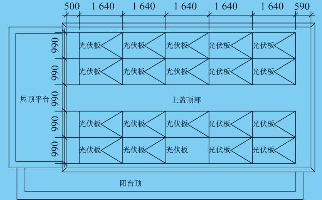
Taking the solar power generation system for village houses in the New Territories of Hong Kong, China as an example, the project is divided into a phase I project and a long-term construction project. The first phase includes the construction of solar power generation systems for various village houses in the New Territories, and the long-term project includes a remote data monitoring and operation platform for solar power generation in village houses in the New Territories. The project is located on the roof of a village house in the New Territories, with a building area of approximately 70 square meters and a photovoltaic power generation area of approximately 32 square meters. The solar power generation capacity is 5.7 kW. Monocrystalline silicon solar photovoltaic panels are installed on the roofs of village houses, with a total of 20 panels in 4 rows and 5 columns. The installation angle of the solar panels is facing south and an elevation angle of 22 °. The installed capacity of solar panels is approximately 5.7 kW. The roof layout of solar photovoltaic panels is shown in Figure 1.
2.1 Performance parameters of solar panels
The solar panel should have a CQC solar product certification certificate, with a protection level of IP65, a maximum snow load greater than 5400 Pa, a maximum wind pressure greater than 2400 Pa, and the product passing PID testing.
The performance parameters of solar panels are shown in Table.
| Material | Nominal power/W | Working voltage/V | Open circuit voltage/V | External dimensions/mm | Protection level | Working current/A | Short circuit current/A | Maximum system voltage/V | Component efficiency/% | Output power/% | PID testing | Maximum snow load/Pa | Maximum wind pressure/Pa |
| Poly silicon | 270 | 30.89 | 38.23 | 1640 × 992 × 40 | IP65 | 8.74 | 9.13 | 1000 | 16.6 | >90 | pass | >5400 | >2400 |
| Monocrystalline silicon | 285 | 31.27 | 38.90 | 1640 × 992 × 40 | IP65 | 9.11 | 9.53 | 1000 | 17.52 | >90 | pass | >5400 | >2400 |
The output power of solar panels is closely related to weather conditions such as light intensity, ambient temperature, and cloudy, sunny, rainy, and foggy weather:
In the formula:
Pref – The maximum output power of the solar panel under standard conditions;
P – The output power of the solar panel under actual conditions;
K – Power temperature coefficient, taken as 0.47%/℃;
Sref – reference value of light intensity under standard conditions, with a base value of 1000 W/m2;
Tref – environmental temperature reference value, with a base value of 25 ℃;
S – actual illumination intensity under actual conditions;
T – ambient temperature under actual conditions.
2.2 Connection method of solar panels
During construction, attention should be paid to connecting the positive and negative poles of 5 solar panels in series, and the positive and negative poles of the solar panels outputted in series should be opposite and not connected incorrectly. The precautions for solar panels are as follows:
(1) The buses of each array are equipped with low smoke, halogen-free, flame-retardant Class A metal armored cables, and the cables are laid in PVC conduit with a diameter of 25mm protection against ultraviolet radiation.
(2) The bracket and foundation of the square array are designed firmly and can withstand the test of the maximum local wind force. The base of the solar panel is supported by a steel frame, and the bottom is made of a fully extended 100mm × Fixed with 12.5mm galvanized channel steel.
(3) Considering seasonal and day night temperature differences, careful installation and adjustment should be made during the installation of battery modules to prevent excessive stress on the glass (such as adding rubber pads and moderate tightness when tightening screws during installation), in order to avoid glass damage.
(4) For the convenience of shunt control, the solar panel array is divided into multiple branches connected to the DC control part. The system is equipped with one photovoltaic array lightning protection combiner box.
(5) To prevent personal contact with the high voltage and high current generated by the solar panel array, the entire solar panel array should be reliably grounded, and the functional grounding should be connected to the grounding busbar at a single point.
(6) Solar panels should be installed on the roof, and good ventilation should be ensured on the back during construction, and lightning protection measures should be taken.
(7) The tempering performance of tempered glass (>3.2 mm) for solar panels meets the national standard GB 15763.2-2005 or the impact resistance performance of packaged components meets the performance indicators specified in GB/T 9535-1998 “Environmental Test Methods for Ground Silicon Solar Cells”. The back panel protective material has good resistance to environmental erosion and insulation ability. The back cover of the solar panel is made of fluoroplastic film, which is white and reflects sunlight. Therefore, it slightly improves the efficiency of the solar panel. Due to its high infrared emissivity, it can also reduce the working temperature of the solar panel, which is beneficial for its efficiency. Fluoroplastic film has the basic requirements of aging resistance, corrosion resistance, and air tightness required for solar panel packaging. The frame is made of hard aluminum alloy, and the surface oxide layer thickness is greater than 10 μ m. Ensure outdoor use for more than 25 years without corrosion, sturdy and durable, with a protection level of IP65.
2.3 Circuit breakers for photovoltaic array protection
The circuit breaker for photovoltaic array protection should adopt a DC arc fault circuit breaker for photovoltaic use (with isolation and load on/off functions), and have no polarity. Its breaking capacity should be greater than the possible reverse fault current. The system is equipped with ground insulation fault detection, protection, and alarm measures. Install an insulation monitor on the DC side, and when the positive or negative pole of the system is directly grounded (i.e. not grounded through resistance), disconnect the grounding of this function at the detection time.
2.4 Solar panels
A total of 20 285 type monocrystalline silicon solar panels were selected, totaling 5.7 kW; Each circuit consists of 2 rows and 5 columns, with a total of 10 285 type monocrystalline silicon solar panels (circuit capacity of 2.85 kW). Two circuits are connected to a solar inverter, with a capacity of 10 kW. Solar inverters and other products should have a CQC solar product certification certificate.
2.5 Inverters
The solar inverter is equipped with anti islanding protection, namely power grid outage and grounding protection, with an inverter efficiency of 94.8%. It has the function of tracking the maximum input power, low output current harmonics, high power factor, and soft start function for output power; It can automatically connect/disconnect from the grid based on sunrise/sunset, with extremely low power consumption at night. The AC side has phase sequence adaptive function, and can still operate normally in case of incorrect sequence; Adopting common mode suppression technology to reduce high-frequency residual current of photovoltaic arrays and reduce external conducted interference; Built in computer control system with the function of recording operating data, detecting and protecting grid side voltage, current, frequency, and islanding; Adopting LCD Chinese human-machine interface; Active power continuously adjustable, reactive power adjustable, high protection level (IP54); Integrated Modbus RTU communication; Provide a multifunctional user interface and communication; There is an upper computer configuration and monitoring software based on professional software systems, which can form a remote monitoring system through communication interfaces and achieve unmanned fully automatic operation.
2.6 Circuit breakers
The solar power generation system is connected to the power grid system at a voltage level of 380 V, and the grid connection points use manual isolation switches and automatic circuit breakers (N2 and N3 switches). The circuit breakers should use mechanical switches with visible breakpoints, and should have short circuit quick break, long delay protection functions, as well as shunt trip, loss of voltage trip, and low voltage blocking closing functions. The customized loss of voltage trip should be set to 20% Ue (10 seconds), and the voltage setting should be set to greater than 85% Ue when detected, while residual current protection should be configured. The circuit breaker should have clear indication of the breaking point and zero breaking function, and should also have auxiliary contacts that reflect the fault and operating status. The system should use a B-type circuit breaker (RCD) with residual current protection/residual current monitoring (RCM) protection that meets the requirements of GB/T 6829-2017 “General Requirements for Residual Current Operated Protective Devices (RCD)”. When the continuous residual current exceeds 10 mA/kVA, the RCM should be able to disconnect from the grid or isolate the faulty photovoltaic module within 0.3 seconds.
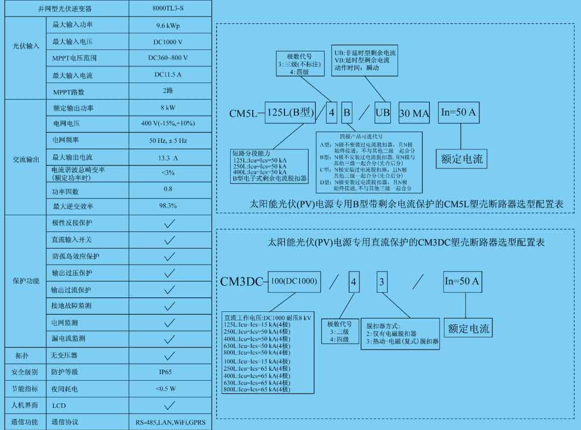
The parameters of the solar inverter and the protection switch are shown in Figure 2.
2.7 Compliance with current national standards
The power quality of the solar power generation system connected to the power grid should comply with the provisions of the current national standard GB/T 29319-2012 “Technical Regulations for the Connection of Photovoltaic Power Generation Systems to Distribution Networks”; When the power quality deviates from the standard and exceeds the limit, the grid connected power generation system should be able to detect the deviation and disconnect it from the grid; The DC current component fed to the power grid should not exceed 0.5% of its rated output AC current or 5 mA (whichever is greater).
2.8 Solar power generation system functions
The solar power generation system is equipped with instruments with communication and metering functions; Equipped with bidirectional active and four quadrant reactive power measurement and event recording functions; Capable of current measurement (including three-phase current, neutral pole current, three-phase current imbalance), voltage measurement (including line voltage, line voltage imbalance, phase voltage imbalance), power measurement (including active power, reactive power, power factor), electrical energy measurement (including active and reactive energy), frequency measurement, etc; Current error accuracy of 0.2 level, voltage error accuracy of 0.2 level
Level, power and electrical energy measurement accuracy of 0.5 level; With communication function, various measurement data and fault information can be transmitted to the remote data monitoring and operation platform of solar power generation in the future.
2.9 Remote data monitoring and operation platform for solar power generation
In the long term, the project will construct a remote data monitoring and operation platform for solar power generation in the entire village house in the New Territories, including an outdoor display screen system, data monitoring and acquisition system, data transmission system, and remote data monitoring and operation platform. The data monitoring and collection system should include solar total radiation sensors, environmental temperature/humidity sensors, photovoltaic module temperature sensors, etc. The data transmission system should include the following functions:
(1) The system is equipped with input measurement ports and operation interfaces that can be connected to external sensors, including 8 analog signals (such as temperature, irradiance, air pressure, humidity, etc.) and 8 digital signals (such as wind speed, smart meters, etc.) input interfaces.
(2) Connect to the inverter collector via RS-485 communication bus to obtain the power generation status of each photovoltaic module and the power generation of each solar inverter.
(3) The system can be connected to an external display screen to display the operation status of solar power generation systems in various village houses, and can also be connected to a remote monitoring platform. The solar inverter is equipped with a WiFi module to achieve wireless remote connection.
The remote data monitoring and operation platform for solar power generation is equipped with an uninterruptible power supply (UPS), and the system data should be able to be stored for more than 5 years, including storing and querying historical operating information and fault records, displaying real-time operating conditions and analyzing operating data. It has a friendly human-machine operation interface and monitoring display interface, and interacts with the remote data center parameters in the specified data format, monitors and records all technical parameters (including environmental parameters such as total solar radiation, environmental temperature, humidity, photovoltaic module temperature, power generation, cumulative power generation, DC side voltage, current, frequency, etc., as well as program control, alarm and other signal switching quantities related to circuit breakers), supporting remote control and remote configuration of power generation system parameters.
If there is an alarm or malfunction in the solar photovoltaic inverter, the monitoring system can notify technical personnel of the current status and cause of the malfunction through voice, graphic flashing, GSM short messages, etc., and quickly troubleshoot. The system sets up a data monitoring and operation cloud server, allowing users to interact with remote monitoring backend in high real-time through mobile apps, computers, and PCs. Users can timely view various operating status and electrical parameters of the photovoltaic system, which intuitively displays electrical circuits, operating curves, and data. In addition, users can perform remote data tuning or operations on the monitoring host or remote monitoring station.
2.10 Lightning protection, grounding system and safety measures
(1) The lightning protection level of rooftop solar panels is Class III. The lightning protection device of the building meets the requirements of preventing direct lightning strikes, lightning induction, and intrusion of lightning waves, and equipotential bonding is set up.
(2) Use galvanized round steel with a diameter of 12mm on the roof as the lightning protection strip and rod, and the grid of the roof lightning protection connection line should not exceed 20m × 20 meters.
(3) Use 40mm at the four corners of the building × 4mm galvanized flat steel is laid as a down conductor. The upper end of the down conductor is welded to the lightning protection strip, and the lower end is welded to the bottom beam of the building foundation and the original grounding electrode. The external wall down lead is led out 1 meter below the outdoor ground and welded to the outdoor grounding wire.
(4) The power supply inlet line should be repeatedly grounded and lightning protection measures should be taken. That is, the cable inlet and outlet lines should be connected to the electrical equipment grounding at the inlet and outlet ends, such as the metal sheath and steel pipes of the cable. The grounding devices of various metal pipes and electrical equipment entering and exiting the building should be connected to the lightning protection grounding device at the inlet and outlet.
(5) The exposed conductive parts of the photovoltaic array and the metal casing of the equipment should be reliably connected by equipotential bonding. The metal frame of photovoltaic modules should be reliably connected to the roof lightning protection device at multiple points through its metal frame, and the connecting parts should be cleaned of non-conductive protective layer; When removing any photovoltaic module, ensure the continuity of grounding.
(6) The bottom and top of vertically laid metal pipes and metal objects should be connected to lightning protection devices.
(7) When the project adopts total equipotential bonding, the total equipotential plate is made of copper plate, and the specific method refers to the national building standard atlas D502 “Equipotential Bonding Installation”. All electrical equipment metal casings that are not normally charged but may exhibit voltage when insulation is damaged should be reliably grounded.
(8) The engineering grounding type adopts TN-C-S system. The lightning protection grounding and electrical equipment protection grounding of this project share a unified grounding electrode, and the grounding resistance is required to be ≤ 1 Ω. If the actual measurement does not meet the requirements, an artificial grounding electrode will be added.
(9) When personnel may come into contact with or approach the solar power generation system, anti electric shock warning signs should be set up. Set up dedicated signs and warning signs (including “warning” and “dual power” warning text and symbol display) on all power equipment equipped with dual power supply to remind maintenance personnel.
2.11 Equipment installation and line laying
(1) The power solar inverter cabinet is designed as an XL-21 fixed cabinet with a protection level of IP65. It is installed on the floor and has a 300mm foundation.
(2) Solar panels are installed overhead at a height of 1.8 meters from the ground, facing south and back north, with a tilt angle of 22 °. They are supported by steel frames, and the bottom is supported by a full length of 100 mm × Fixed with 12.5mm galvanized channel steel (installation height not exceeding 2.5m on the rooftop and extending beyond the outer wall not exceeding 0.75m).
(3) The installation area of solar panels shall not exceed village houses
50% of the top area, each solar panel group occupies an area of ≤ 5 m2, and the spacing between each group is ≥ 1 m. One side of the solar panel installation area should reserve a 1.05 meter evacuation passage to the parapet wall, and a 1.05 meter evacuation passage should be left from the solar panel installation area to the rooftop exit.
(4) The DC cable from the solar panel to the solar inverter uses a solar specific cable PV1-F 2Pfg 1169, and the AC incoming cable from the solar inverter to the grid uses a YJV copper core cable.
(5) Install a fire dry powder fire extinguisher on the rooftop.
(6) Construction and installation personnel should take anti electric shock measures and comply with the following regulations: they should wear insulated shoes, low-voltage insulated gloves, and use insulated tools; When there are overhead power lines above the installation location of the solar power generation system, protective and isolation measures should be taken; Work should not be carried out on rainy, snowy, or windy days.
2.12 System detection
(1) Preparation work before on-site testing. Check the electrical wiring connections of the entire solar power generation system, conduct anti islanding tests (connect the voltage terminal and current transformer of the oscilloscope/data recorder to the four pole lockable main isolation switch of the solar power generation system), close the four pole isolation switch, simulate system accidents by opening the four pole lockable main isolation switch, and record the voltage and current waveforms of the oscilloscope/data recorder to confirm that the anti islanding power outage time is less than 200 ms; The delay in reconnecting the system to the power grid should be 300 seconds; Record the harmonic components in voltage and current waveforms using an oscilloscope/data recorder, and review and download the waveforms and data recorded in the oscilloscope/data recorder.
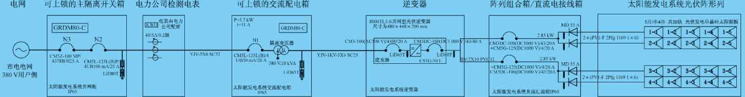
(2) On site testing for connection to the power grid. Check the installation, grounding, and electrical line connection of the power grid connection part, conduct harmonic current distortion testing according to the required steps of the preparation work, verify that the anti islanding operation device of the system can meet the anti islanding operation power-off time of less than 200 ms, measure the impedance of the grounding fault circuit, the impedance of the phase to neutral line circuit, and the circuit breaking time of the residual current action protector of the system, and check the warning signs of each DC and dual power supply during the connection of the solar power generation system to the power grid. The village house solar power generation system is shown in Figure 3.
3. Investment return on solar power generation projects in village houses in Hong Kong
Renewable energy generation in Hong Kong, China has an on grid electricity price, which is higher than the general electricity price level and sold to power companies. The on grid electricity price is set as follows: system power generation capacity ≤ 10 kW, 5 yuan; 10 kW < system power generation capacity ≤ 200 kW, 4 yuan; 200 kW < system power generation capacity ≤ 1 MW, 3 yuan. Taking the solar power generation system of a single New Territories village house as an example, the installed capacity of the solar panels is about 5.7 kW, and the annual power generation is about 4500 kWh, resulting in an annual electricity revenue of about 22000 yuan. The investment cost of solar power generation system is approximately 60000 yuan. Therefore, the investment payback period for a single New Territories village house solar power generation system is about 4 years, with a high return on investment.
4. Conclusion
With the policy support of the Hong Kong government for renewable energy, investors will increase their investment in solar power generation systems and renewable energy generation systems, which can avoid land restrictions in Hong Kong, promote changes in energy production and utilization, optimize energy supply structure, and achieve the goal of the Hong Kong Climate Action Blueprint 2030+, which is to use renewable energy such as wind and solar power to generate 3% to 4% of Hong Kong’s total electricity consumption by 2030.