Based on the proposed modulation strategy, a loss model for the two-stage solar inverter proposed in this paper will be established under the cascaded control strategy. The losses of solar inverters mainly include conduction losses, switching losses, and inductance losses.
When the solar inverter is in operation, the current passes through the power component and generates a voltage drop at both ends. The product of this voltage drop and current is the conduction loss of the component. In solar inverter systems, conduction losses mainly include the conduction losses of IGBTs and diodes. Taking a certain model of IGBT as an example, the voltage drop and current curve can be fitted as a linear function by searching the data manual.
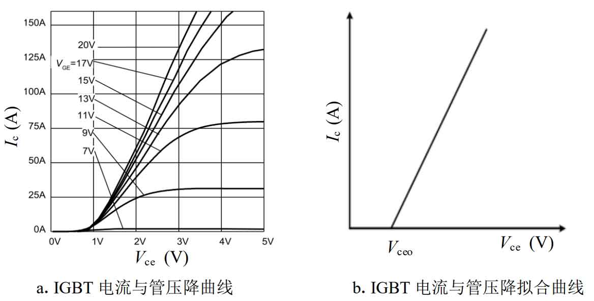
Figure 1 (a) shows the IGBT current and tube voltage drop curve provided by the manufacturer, which is linearly fitted to the linear function shown in Figure 1 (b). Ic is the collector current, and Vce is the voltage between the collector and emitter, i.e. the conduction tube voltage drop. Therefore, the conduction tube voltage drop of IGBT can be described as:
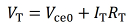
Among them, Vce0 is the threshold voltage for IGBT conduction; IT is the average conduction current of IGBT; RT is the equivalent resistance of IGBT. By substituting the average current flowing through the IGBT into the above equation, the voltage drop of the conduction tube can be calculated, and the product of the two is the average conduction loss.
The calculation method for the conduction loss of a diode is similar to the above method, and the relationship between the conduction current of the diode and the voltage drop of the conduction tube is fitted as a linear relationship through a data manual. First, calculate the average current when the diode is conducting, and then calculate the voltage drop of the transistor according to the above relationship. Multiply the voltage drop of the transistor with its average current to obtain its average conduction loss.
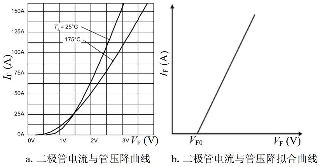
IF is the conducting current of the diode, and VF is the conducting voltage of the diode. According to Figure 2, the voltage drop relationship of the diode conduction tube can be obtained by fitting:
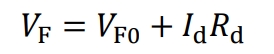
Among them, VF0 is the threshold voltage for diode conduction; Id is the average conducting current of the diode; Rd is the equivalent conducting resistance of a diode.
There are a total of 4 IGBT operations in the front-end circuit, and the T1 and T2 operating ranges of the switching tubes are complementary. In the following calculation process, it can be equivalent to T1 continuous operation, and its average conduction loss can be expressed as:
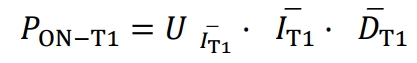
IT1 is the average value of the current flowing through T1, which essentially provides current to the subsequent three-phase load through the busbar and midpoint. The three-phase current has a total sum of two-phase currents that is equal in magnitude and opposite in direction to the current of the other phase.
Therefore, the average current flowing through T1 should be half of the total average current value of the three phases:

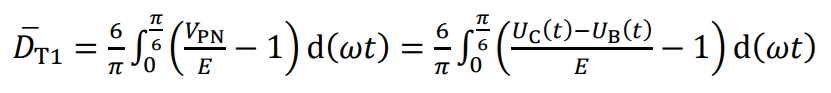
At the same time, it is necessary to calculate the average duty cycle of T1 DT1, and obtain the relationship between DT1 and bus voltage from the formula. Based on the symmetry in Figure 3, calculate the average duty cycle of T1:
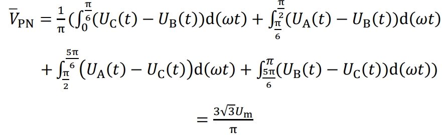
According to the symmetry of the bus voltage in Figure 3, the average value of the bus voltage can be calculated using the formula:
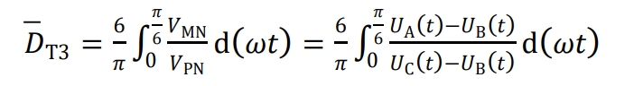
Due to the symmetry of the circuit structure and working process, the conduction losses of T3 and T4 are equal. Therefore, a conduction loss model for T3 can be established first, and the average current flowing through T3 can be calculated by referring to the above calculation process:
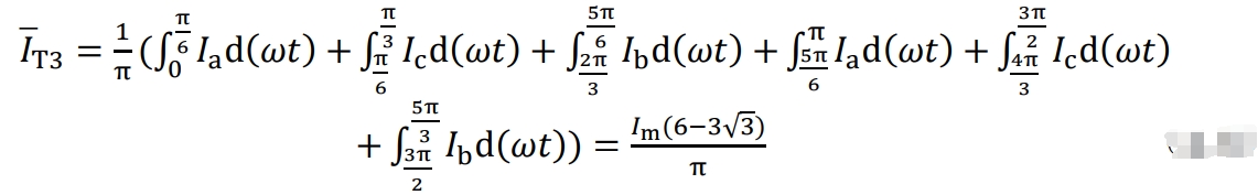
At the same time, calculate the average duty cycle of T3 DT3. According to the formula, during the operation of T3, DT3 is equal to the ratio of midpoint voltage to bus voltage. Based on the symmetry of Figure 3, calculate the average duty cycle of T3 from 0 to π/6, which is DT3:
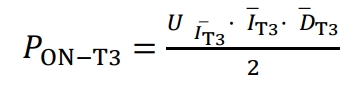
Due to T3 only operating for half a cycle of a fundamental wave, its conduction loss can be expressed as:
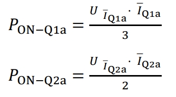
For the later stage solar inverter, the conduction loss of the three-phase bridge arm is equal, and the conduction loss of the A-phase bridge arm can be calculated first. The conduction losses of A-phase bridge arms Q1a and Q4a are equal, while the conduction losses of Q2a and Q3a are equal. The conduction time of Q1a within one fundamental cycle is Tc/3, therefore the duty cycle of Q1a is 1/3. The effective conduction time of Q2a is Tc/2, so its duty cycle is 1/2. First, calculate the average current of Q1a and Q2a:
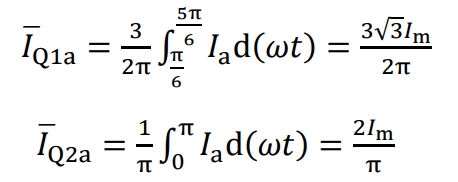
The conduction losses of Q1a and Q2a can be expressed as:
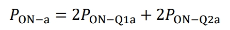
The conduction loss of the A-phase bridge arm IGBT can be recorded as:
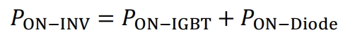
IGBT total conduction loss of two-stage solar inverters:

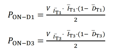
Two stage solar inverters simultaneously have diode conduction losses. The conduction losses of diodes D2 and D1 in the front-end circuit are the same, while the conduction losses of D3 and D4 are the same. Its function is to continue flowing to the inductor when the IGBT is disconnected.
The conduction loss of diodes D1 and D3 can be expressed as:
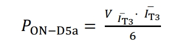
In the later stage inverter circuit, there are a total of 6 clamping diodes with equal conduction losses, and D5a can be calculated first conduction loss, whose current is provided by inductor L3, has an effective conduction time of Tc/6.
The total diode conduction loss of the two-stage solar inverter is:

Total conduction loss of two-stage solar inverters: