
Lithium-ion batteries have established themselves as the dominant energy storage technology for a wide array of applications, from portable electronics to electric vehicles and grid-scale storage, primarily due to their high energy density, long cycle life, and low self-discharge rate. However, a critical challenge that shadows their widespread adoption is the risk of thermal runaway (TR)—a dangerous, self-accelerating exothermic chain reaction within the cell leading to rapid temperature rise, often accompanied by venting, fire, or explosion. Among the various lithium-ion chemistries, such as those based on LiCoO2 (LCO), LiMn2O4 (LMO), and LiNixMnyCozO2 (NMC), the lithium iron phosphate (LiFePO4 or LFP) battery is widely recognized for its superior intrinsic safety and lower thermal runaway risk.
The exceptional safety of the LiFePO4 battery stems from the fundamental stability of its olivine-type cathode structure. The strong P–O covalent bonds in the phosphate polyanion (PO43-) significantly inhibit the release of oxygen from the cathode lattice at elevated temperatures, unlike layered oxide cathodes (e.g., LCO, NMC) which readily decompose and release oxygen. This oxygen starvation during thermal abuse drastically limits the amount of electrolyte available for combustion, thereby reducing the total heat generated and the overall severity of a thermal runaway event. For instance, theoretical calculations estimate that a standard 18650 LiFePO4 cell releases approximately 0.5 g of oxygen, whereas a comparable LCO cell can release up to 3.25 g. The amount of oxygen available is also a function of the cell’s state of charge (SOC); a fully charged cathode (delithiated) offers more oxygen for exothermic reactions. Remarkably, even at 0% SOC, trace oxygen release is possible due to irreversible capacity loss over the battery’s lifecycle, preventing the cathode from being fully lithiated.
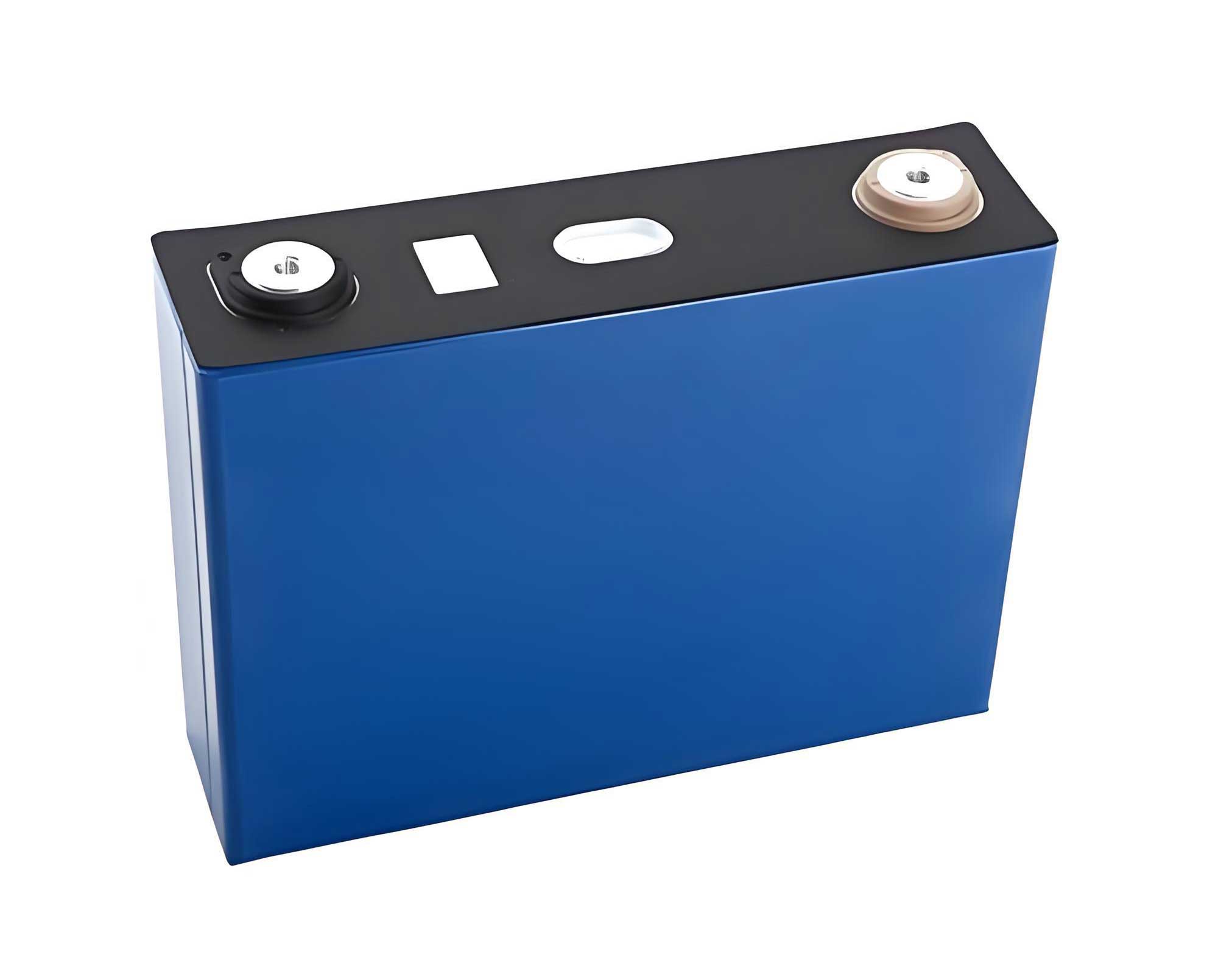
Despite this inherent stability, a LiFePO4 battery is not immune to thermal runaway. Under severe abusive conditions, the internal temperature can rise sufficiently to trigger a sequence of decomposition reactions, culminating in cell failure. This article provides a comprehensive review of the causes, progression mechanisms, influencing factors, and mitigation strategies for thermal runaway in LiFePO4 batteries, consolidating current research to offer solutions for their safe application throughout their lifecycle.
Causes and Sequential Stages of Thermal Runaway in LiFePO4 Batteries
Thermal runaway in a LiFePO4 battery is typically initiated by one or more abusive conditions that drive the cell temperature beyond its safe operating window. These abuses are commonly categorized into three types:
| Abuse Category | Description | Primary Effect |
|---|---|---|
| Mechanical Abuse | Physical deformation, crush, or penetration of the cell casing (e.g., from impact or nail penetration). | Internal short circuit (ISC) creation, rapid localized Joule heating. |
| Electrical Abuse | Operation outside specified limits: Overcharge, over-discharge, or external short circuit (ESC). | Parasitic side reactions, plating, gas generation, and excessive Joule heating. |
| Thermal Abuse | Exposure to external heat sources or internal heat generation from poor thermal management. | Accelerates all decomposition reactions, triggering the TR chain. |
Among these, overcharge is a particularly critical and well-studied trigger. The progression of thermal runaway in a LiFePO4 battery due to overcharge can be delineated into six sequential stages, each characterized by distinct physicochemical phenomena.
| Stage | Approx. Temp. Range | Key Events & Phenomena | Observable Effects |
|---|---|---|---|
| 1. Lithium Plating | Ambient to ~60°C | Under overcharge, lithium ions exceed the intercalation capacity of the anode. Metallic lithium (Li0) begins to plate on the graphite surface, forming lithium dendrites. | Cell voltage plateaus at a high value; slight temperature increase. |
| 2. SEI Decomposition | 80°C – 120°C | The Solid Electrolyte Interphase (SEI) layer, which is metastable, decomposes exothermically. This reaction generates gases like C2H4 and CO2. | Noticeable surface temperature rise; cell swelling begins; pressure relief valve (vent) may open. |
| 3. Anode-Electrolyte Reaction | 120°C – 250°C | With the SEI layer compromised, the lithiated graphite (LiC6) reacts exothermically with the electrolyte. The plated lithium metal is highly reactive and participates vigorously. | Rapid temperature increase; significant gas generation and venting. |
| 4. Separator Failure & Internal Short | 130°C – 190°C+ | The polyolefin separator undergoes melting and shrinkage (∼130°C), then decomposition (∼190°C). This leads to a large-area internal short circuit (ISC) between the anode and cathode. The LiFePO4 cathode itself starts to decompose, though more slowly than other chemistries. | Voltage drop; sudden, massive heat generation (“thermal runaway”); violent electrolyte vapor ejection. |
| 5. Electrolyte Decomposition & Combustion | >200°C | Remaining electrolyte solvents (e.g., EC, DEC) and salts (e.g., LiPF6) decompose and/or combust if oxygen is present from vented air or cathode decomposition. | Smoke, possible open flame (fire). |
| 6. Propagation (in a pack) | N/A | The intense heat and ejected flaming material from the failing cell act as an external thermal abuse source for adjacent cells, potentially causing TR propagation through the module. | Chain reaction failure of multiple LiFePO4 battery cells. |
The critical temperature for the onset of self-heating ($T_{onset}$) in a LiFePO4 battery is generally between 100°C and 120°C, which is relatively high compared to some other chemistries. The heat generation rate ($\dot{Q}_{gen}$) during these stages can be modeled as the sum of contributions from various reactions:
$$
\dot{Q}_{gen} = \sum_i A_i \exp\left(-\frac{E_{a,i}}{RT}\right) + I^2 R_{isc}(T) + \dot{Q}_{joule}
$$
where $A_i$ and $E_{a,i}$ are the pre-exponential factor and activation energy for the i-th chemical reaction (SEI decomposition, anode-electrolyte, etc.), $R$ is the gas constant, $T$ is temperature, $I$ is the short-circuit current, $R_{isc}$ is the internal short-circuit resistance, and $\dot{Q}_{joule}$ is the Joule heat from external abuse.
Influencing Factors and Mitigation Strategies for LiFePO4 Battery Thermal Runaway
The propensity, severity, and consequences of a thermal runaway event in a LiFePO4 battery are influenced by numerous factors. Understanding these allows for the design of effective prevention and mitigation strategies at the cell, module, and system levels.
1. State of Charge (SOC)
The SOC is perhaps the most significant factor determining the severity of thermal runaway. A lower SOC implies a more lithiated (and thus more stable) cathode and a less reactive anode. Research on 18650 LiFePO4 cells has demonstrated a critical threshold:
- SOC ≤ 28%: Cells generally do not undergo thermal runaway when heated; they may vent but do not violently combust.
- SOC > 28%: The severity (peak temperature, violence) of thermal runaway increases with SOC. A fully charged LiFePO4 battery will experience the most severe event.
This has direct implications for storage and transportation safety regulations, advocating for shipping LiFePO4 battery packs at a reduced SOC (e.g., 30% or lower).
2. Overcharge Rate (C-rate)
The current rate during overcharge significantly impacts the TR characteristics. Studies on large-format (e.g., 60 Ah) LiFePO4 batteries show an inverse relationship between overcharge C-rate and TR severity:
- Low C-rate (e.g., 0.5C): Leads to a longer time to TR, allowing more extensive side reactions and lithium plating. This results in a higher total energy release during TR, causing a larger temperature rise and posing a greater propagation risk to neighboring cells.
- High C-rate (e.g., 2C): Causes faster voltage rise and earlier triggering of safety devices. The TR event, while rapid, releases less total chemical energy, resulting in a lower peak temperature and significantly reduced propagation risk.
The heat accumulation ($Q_{acc}$) before venting can be approximated as a function of current $I$ and time $t_{vent}$: $Q_{acc} \propto I^2 \cdot t_{vent}$. At high C-rates, $t_{vent}$ is shorter, limiting $Q_{acc}$.
3. Electrolyte Composition
The thermal stability of the electrolyte directly affects the TR onset temperature and heat release. Research comparing lithium salts found that electrolytes using lithium bis(oxalato)borate (LiBOB) exhibit superior thermal stability compared to those based on LiPF6. The BOB anion lacks fluorine and has a stable tetrahedral structure, making it less prone to generating Lewis acids (like PF5) that catalyze electrolyte decomposition. Therefore, formulation of the LiFePO4 battery electrolyte with thermally stable salts and additives is a key cell-level safety enhancement.
4. Thermal Management System (TMS) Design
Effective cooling is paramount for preventing thermal abuse and mitigating propagation. The design of coolant flow paths within a battery module greatly affects temperature uniformity. A study on 26650 LiFePO4 battery modules compared four cooling channel designs:
| Design | Description | Thermal Performance |
|---|---|---|
| Parallel Flow | Coolant flows simultaneously through multiple parallel channels. | Can lead to uneven flow distribution and temperature gradients. |
| Serpentine Flow | Coolant follows a long, winding path. | Good cooling but may cause high pressure drop and inlet-outlet温差. |
| Serial Flow | Coolant passes through cells or cooling plates one after another. | Promotes the best thermal balance (minimum cell-to-cell温差) for LiFePO4 battery packs, meeting optimal operating temperature requirements and reducing hot spot-induced TR risk. |
The governing equation for heat removal by a liquid-cooled TMS is:
$$
\dot{Q}_{cool} = \dot{m} c_p (T_{out} – T_{in})
$$
where $\dot{m}$ is the coolant mass flow rate, $c_p$ is its specific heat capacity, and $T_{in}$/$T_{out}$ are the inlet/outlet temperatures. An optimized TMS maximizes $\dot{Q}_{cool}$ and minimizes the maximum cell temperature $T_{max}$.
5. Early Detection and Active Suppression
Monitoring and early intervention are critical system-level strategies.
- Temperature Monitoring: Since the self-heating onset for a LiFePO4 battery is ~100-120°C, setting a safety alarm threshold between 60°C and 100°C provides a critical warning window. Upon alarm, charging/discharging should cease, and cooling should be maximized.
- Active Fire Suppression: Experiments using fine water mist in an explosion suppression chamber have shown effectiveness. If applied immediately when the pressure relief valve opens (venting), the mist can rapidly cool the cell surface and suppress ignition. Crucially, any external heat source must be removed concurrently; otherwise, the mist may fail to prevent fire.
6. Cell and Module Design Features
Several design innovations can enhance the safety of the LiFePO4 battery:
- Fusible Links/Current Interrupt Devices (CID): These components are designed to melt or disconnect at a specific temperature or current, breaking the electrical circuit and stopping abusive currents.
- Ceramic-Coated Separators: Separators with ceramic (e.g., Al2O3) coatings provide significantly improved thermal stability, resisting shrinkage and maintaining integrity at much higher temperatures (>200°C), thereby delaying or preventing internal short circuits.
- Positive Temperature Coefficient (PTC) Devices: These components increase resistance dramatically with temperature, limiting current during a fault.
Conclusion and Integrated Safety Philosophy
The LiFePO4 battery stands out for its excellent thermal and chemical stability, offering a fundamentally safer lithium-ion chemistry. However, as detailed in this review, it remains susceptible to thermal runaway under mechanical, electrical, or thermal abuse conditions. The process follows a well-defined sequence of stages, from lithium plating and SEI decomposition to separator failure and violent exothermic reactions.
The severity of a thermal runaway event in a LiFePO4 battery is strongly modulated by factors such as State of Charge, overcharge rate, electrolyte formulation, and the effectiveness of the thermal management system. A multi-layered, defense-in-depth safety approach is essential for risk mitigation:
- Prevention (Cell & BMS Level): Utilize stable materials (LFP cathode, ceramic separators, LiBOB-enhanced electrolytes), incorporate internal safety devices (CID, PTC), and enforce strict BMS limits on voltage, current, and temperature.
- Detection (System Level): Implement dense, real-time monitoring of cell voltages, pack currents, and especially temperatures—with alarms set well below the known onset of self-heating for the LiFePO4 battery.
- Containment & Mitigation (Module & Pack Level): Design robust thermal management systems (e.g., optimized serial flow cooling) to maintain uniformity and prevent hotspots. Integrate fire suppression systems (e.g., fine water mist) and design modules with thermal barriers to slow or prevent propagation between LiFePO4 battery cells.
- Operational Protocols: Store and transport LiFePO4 battery systems at a partial state of charge (e.g., 30-50% SOC) to intrinsically reduce energy available for a runaway reaction.
By integrating insights from materials science, electrochemistry, and thermal engineering, the safety risks associated with LiFePO4 batteries can be effectively managed. This holistic understanding enables the continued and expanded use of this robust and safe battery technology across demanding applications, ensuring reliability throughout its entire lifecycle.