
In the face of escalating global electricity demand and mounting environmental pressures, modern power systems are rapidly evolving towards a paradigm characterized by a high penetration of renewable energy sources and a high proportion of power electronic devices, often termed the “dual-high” trend. While this transition is essential, it introduces significant challenges to grid stability. The inherent intermittency of renewables and the reduced system inertia associated with power electronic converters can weaken the overall grid strength, making frequency and voltage regulation more complex. In this context, Battery Energy Storage Systems (BESS) have emerged as a cornerstone technology for enhancing grid flexibility and reliability. Their roles are multifaceted, ranging from providing crucial frequency regulation and voltage support, enabling higher renewable integration, participating in energy arbitrage (peak shaving), to offering backup power during faults. The application of grid-forming (GFM) control techniques to BESS inverters is particularly promising for bolstering system stability by providing synthetic inertia and robust voltage source characteristics. Consequently, the intrinsic reliability and stability of the BESS itself become paramount. Among the various metrics for assessing this reliability, the insulation withstand capability stands as a critical indicator, directly impacting safety, longevity, and operational integrity.
Partial discharge (PD), a localized electrical breakdown within a dielectric insulation system under high electric stress, is a primary precursor to insulation failure in high-voltage equipment. Regardless of its form—be it corona discharge from sharp conductors, surface tracking, or internal discharges within voids—the cumulative degradation caused by PD can severely compromise insulation, leading to catastrophic failures. For a battery energy storage system, which integrates high-voltage DC battery strings with sensitive monitoring and control electronics, understanding and mitigating insulation and PD risks is fundamental to ensuring its long-term, reliable operation. This research focuses specifically on the reliability enhancement of the core battery energy storage system unit—the integrated assembly of battery cells, mechanical structure, wiring harnesses, and the Battery Management Unit (BMU). We investigate the insulation withstand boundaries, validate performance under simulated high-altitude conditions, and meticulously analyze the impact of wiring harness defects, a common source of PD, on the overall system reliability.
System Composition and the Battery Unit
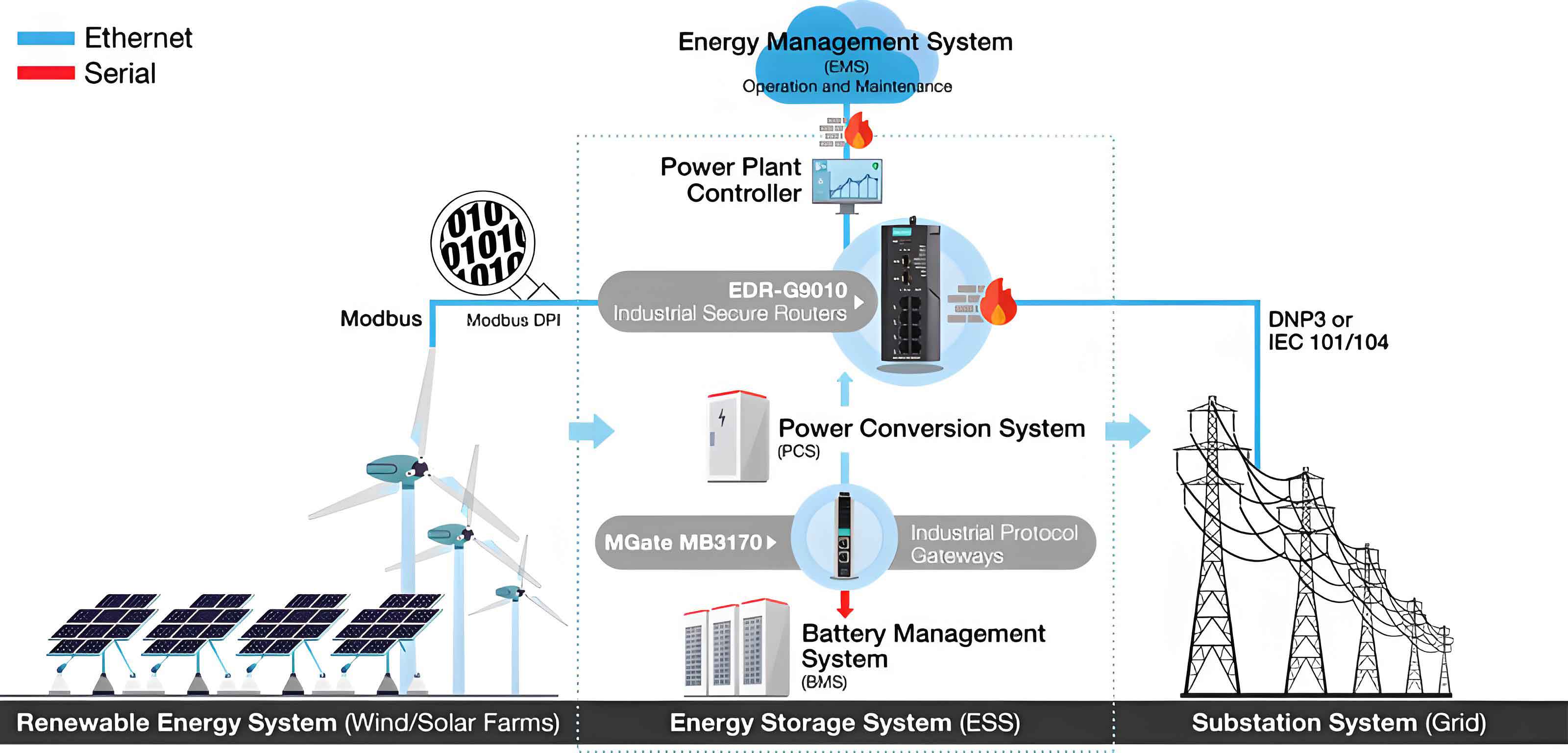
A complete grid-connected battery energy storage system typically comprises four main subsystems: the battery storage unit, the Power Conversion System (PCS), the Energy Management System (EMS), and the Battery Management System (BMS). The BMS is hierarchically organized, including cell monitoring Battery Management Units (BMUs), cluster controllers (BCMUs), and stack controllers (BSMUs). The fundamental building block under study here is the battery unit or module, which includes the electrochemical cells (e.g., lithium-ion), the enclosing mechanical framework (busbars, thermal management interfaces, casing), associated voltage and temperature sensing wiring harnesses, and the local BMU responsible for monitoring that specific module.
Fundamentals of Insulation Withstand and Partial Discharge
Insulation withstand testing is a diagnostic technique used to evaluate the ability of electrical equipment insulation to tolerate specified over-voltages without breakdown. The overall insulation strength of a device is defined by the highest test voltage (in kV) it can withstand. PD testing, on the other hand, detects and quantifies the low-energy discharges that occur within or on the surface of insulation when the local electric field exceeds a critical threshold but is insufficient to cause immediate complete breakdown. These discharges erode insulation over time. In air at standard temperature and pressure (STP: 20°C, 101.325 kPa), the breakdown field strength in a uniform electric field is approximately 30 kV/cm. This serves as a fundamental reference, though real-world conditions involving non-uniform fields, contamination, and material interfaces significantly lower the practical withstand voltage. Common PD mechanisms relevant to a battery energy storage system include:
- Corona Discharge: Occurs at sharp points or edges of conductors where the electric field is highly concentrated.
- Surface Discharge: Tracking along the surface of insulation due to contamination or moisture.
- Internal/Void Discharge: Occurs within gas-filled cavities or delaminations inside solid insulation, which is particularly destructive as it chemically degrades the surrounding material.
The electrical principle for testing the insulation and withstand voltage of a battery module is illustrated in the following equivalent circuit, where a DC test voltage \( V_{test} \) is applied between the battery poles (either positive or negative) and the grounded equipment chassis, and the resulting leakage current \( I_{leak} \) is measured.
$$ I_{leak} = \frac{V_{test}}{R_{insulation}} $$
Where \( R_{insulation} \) is the cumulative insulation resistance of all paths from the live parts to ground. While the test principle is similar for insulation resistance (IR) and dielectric withstand voltage (DWV) tests, the pass/fail criteria differ. IR testing measures the resistance value at a specified DC voltage (e.g., 1000V), typically requiring a minimum value (e.g., >1 MΩ). DWV testing applies a higher voltage (e.g., several kV) for a specified duration (e.g., 60 seconds) and requires that the leakage current remains below a maximum limit, with no flashover or breakdown.
Methodology: Test Principles and Layered Approach
The core challenge in assessing a battery energy storage system unit is its nature as an “active system”—it contains its own internal voltage sources (the series-connected cells). During external insulation testing, the internal cell potentials algebraically superimpose onto the applied test voltage, a phenomenon we term “potential superposition.” This means different points within the battery string experience different potentials relative to ground during the test. For a 1500V DC system, applying a 2.5kV test voltage to the negative terminal could theoretically subject the furthest positive-end components to a potential difference approaching \( V_{test} + V_{system} = 2.5kV + 1.5kV = 4.0kV \).
To systematically deconstruct this, we adopted a “layered decoupling and stepwise superposition” methodology. The battery unit’s insulation integrity is determined by the weakest link among three key subsystems: 1) the battery body (cells + main structure), 2) the secondary sensing wiring harness, and 3) the BMU printed circuit board (PCB). We designed test sequences to isolate and evaluate each subsystem’s contribution to the overall withstand capability.
The test standards referenced are based on GB/T 36276-2018 for lithium-ion batteries, which specifies an insulation test voltage of 2.5kV and a withstand voltage of 3.8kV for a 1500V system. Considering the potential superposition effect and a safety factor of 1.1, the effective required insulation capability for internal components rises to approximately 4.4kV. Furthermore, for high-altitude applications, insulation strength derating must be considered. The relationship between altitude and withstand voltage is often expressed as:
$$ U_{H} = \frac{U_0}{k} $$
Where \( U_{H} \) is the required withstand voltage at altitude \( H \), \( U_0 \) is the sea-level withstand voltage, and \( k \) is the altitude correction factor. A common approximation for altitudes up to 4000m is a 1% reduction in withstand strength per 100m increase in altitude. Thus, the withstand voltage requirement at a specific altitude \( H \) (in meters) can be estimated as:
$$ U_{required}(H) \approx \frac{U_{std}}{ \left[1 – (H-1000) \times 0.01 \right] } \quad \text{for } H > 1000m $$
For a target application at 4800m, and using the standard 3.8kV as a base, the derated requirement at test altitude (simulated) must be significantly higher to ensure adequate margin at operating altitude.
Test Schemes and Parameters
The following tables outline the structured test schemes for both Insulation Resistance (IR) and Dielectric Withstand Voltage (DWV) tests. Condition 1 serves as a baseline test with a BMU simulator (“BMU工装”), Condition 2 tests the fully integrated unit with the actual BMU, and Condition 3 tests the battery body alone with sensing harnesses removed, used for troubleshooting if failures occur earlier.
| Condition | Configuration | Test | Pass Criteria & Notes |
|---|---|---|---|
| 1 | Battery Module + BMU Simulator | Positive-to-Ground Negative-to-Ground |
No flashover/breakdown. Insulation Resistance > threshold. |
| 2 | Battery Module + Actual BMU + Harness | Positive-to-Ground Negative-to-Ground |
No flashover/breakdown. BMU must remain functional post-test (communications normal). |
| 3* | Battery Module (Harness Removed) | Positive-to-Ground Negative-to-Ground |
No flashover/breakdown. (*Executed only if Condition 1 or 2 fails). |
| Condition | Configuration | Test | Pass Criteria & Notes |
|---|---|---|---|
| 1 | Battery Module + BMU Simulator | Positive-to-Ground Negative-to-Ground |
No flashover/breakdown. Leakage current < limit. |
| 2 | Battery Module + Actual BMU + Harness | Positive-to-Ground Negative-to-Ground |
No flashover/breakdown. Leakage current < limit. BMU functional. |
| 3* | Battery Module (Harness Removed) | Positive-to-Ground Negative-to-Ground |
No flashover/breakdown. Leakage current < limit. (*Executed only if Condition 1 or 2 fails). |
To investigate the influence of wiring harness defects, we defined specific experimental variables: presence of a sharp point (“tip”) on the harness, distance (d) between this tip and the grounded frame, and the number/type of insulation layers. The electric field \( E \) at the tip of a protrusion can be approximated by:
$$ E_{tip} \approx \frac{V}{r} $$
Where \( V \) is the potential difference and \( r \) is the radius of curvature of the tip. A smaller \( r \) (sharper tip) leads to a much higher localized electric field, drastically increasing PD risk.
Results and Discussion
1. Validation of the Potential Superposition Phenomenon
Testing a complete 1500V battery unit confirmed the theoretical potential superposition. When a DC voltage \( V_{test} = 500V \) was applied between the NEGATIVE terminal and ground, the voltage measured from the first cell (at the negative end) to ground was ~500V. However, the voltage from the \(a\)-th cell in the string to ground was approximately \( 500V + (a-1) \times V_{cell} \), where \( V_{cell} \) is the nominal cell voltage (~3.2V). Similarly, with \( V_{test} \) applied to the POSITIVE terminal, the \(a\)-th cell voltage to ground was \( 500V – (a-1) \times V_{cell} \). This proves that during an external test, internal series-connected cells experience a linearly graded potential relative to ground. For a full 2.5kV test on the negative pole of a 1500V system, components at the positive end could be stressed at nearly 4.0kV. This justifies designing all internal components (structure, harness, BMU) for a minimum of 4.4kV to include a safety margin.
2. Insulation Capability Boundary and Harness Impact
The baseline test (Condition 1 with no harness defects) showed excellent performance, with insulation resistance exceeding \(10^4\) MΩ at 5kV—the limit of our test equipment. This indicates that a perfectly constructed battery energy storage system unit has inherent insulation capability far beyond the 2.5/4.4kV requirement. However, introducing controlled defects in the wiring harness revealed significant vulnerabilities.
| Case | Harness Tip? | Tip-Frame Distance (d) | Insulation Wrapping | Result at 5kV | Failure Mode |
|---|---|---|---|---|---|
| 1 (Ref) | No | N/A | Std. heat-shrink + cloth tape | PASS (>10⁴ MΩ) | None |
| 2 | Yes | 0 mm | Std. heat-shrink + cloth tape | FAIL at ~3kV | Audible discharge, BMU damaged, comms lost. |
| 3 | Yes | 2 mm | Std. heat-shrink + cloth tape | FAIL at ~3.5kV | Discharge, BMU damaged. |
| 4 | Yes | 4 mm | Std. heat-shrink + cloth tape | PASS | No discharge, system intact. |
The data clearly demonstrates that a sharp point on the wiring harness, especially when in close proximity (d < 4mm) to the grounded frame, acts as a focal point for discharge. The intense local electric field induces PD, which in these tests was severe enough to couple transients into the BMU via the sensing lines, causing permanent damage. This highlights the wiring harness as a critical reliability component in a battery energy storage system.
3. Dielectric Withstand Voltage Boundary and High-Altitude Implication
Withstand voltage tests followed a similar pattern. The defect-free unit withstood 7.4kV easily, passing the test for a 4800m-altitude application as calculated. Introducing a harness tip (even at d > 4mm) lowered the withstand threshold, causing failure between 7.2kV and 7.8kV. However, adding extra insulation layers (e.g., three additional layers of electrical tape) over the defect improved the withstand voltage to 8.8kV, though failure eventually still occurred via the defect path, damaging the BMU.
| Case | Harness Tip? | Tip-Frame Distance (d) | Insulation Wrapping | Withstand Result | Notes |
|---|---|---|---|---|---|
| A (Ref) | No | N/A | Std. heat-shrink + cloth tape | PASS @ 7.4kV | Leakage current < 0.1mA |
| B | Yes | >4 mm | Std. heat-shrink + cloth tape | FAIL @ 7.2kV | Discharge, BMU damaged. |
| C | Yes | >4 mm | Std. wrapping | FAIL @ 7.8kV | Discharge, BMU damaged. |
| D | Yes | >4 mm | Std. + 3x elec. tape | FAIL @ 8.8kV | Higher threshold but BMU failed. |
These results allow us to map the idealized withstand capability boundary of a battery energy storage system unit. With perfect construction, the unit can exceed 8.0kV DC withstand voltage. Applying the altitude derating formula in reverse:
$$ U_{test} = U_{required}(4800) \times \left[1 – (4800-1000) \times 0.01 \right]^{-1} $$
Assuming \( U_{required}(4800) = 3.8kV \), the factor is \( [1 – 38 \times 0.01]^{-1} = (0.62)^{-1} \approx 1.61 \), giving \( U_{test} \approx 6.12kV \). Our unit withstanding 7.4kV provides a comfortable margin, confirming feasibility for high-altitude deployment. However, the presence of even minor manufacturing defects like a sharp wire end can erode this margin significantly and introduce a latent failure risk.
4. Reliability Enhancement Strategies for Battery Energy Storage Systems
Based on the failure analysis, targeted improvements can be implemented during the design and manufacturing of the battery energy storage system to drastically enhance reliability:
- Structural Design Improvements:
- Mandate minimum creepage and clearance distances. Our tests suggest a minimum air gap (d) of 4mm is critical for voltages in this range, but larger margins should be designed where possible.
- Implement insulating barriers or shrouds between wiring harnesses and the metal frame. Using insulating coatings or liners on the inside of the battery cabinet can prevent discharge even if a wire comes loose.
- Use rounded, smooth edges on all metallic components near high-voltage wiring to avoid creating external field concentration points.
- Wiring Harness and Process Improvements:
- Eliminate sharp points at all costs. Replace soldered joints on sense wires with insulated crimp connectors or use potting compounds to create a smooth, blob-free interface.
- Implement a robust multi-layer insulation protocol for all sense wire terminations. A suggested standard could be: primary insulation (wire jacket) → adhesive-lined heat-shrink sleeve → multiple layers of high-dielectric-strength tape (e.g., Kapton®) → final bundling with non-abrasive cloth tape.
- Secure harnesses firmly using insulated clamps or ties to prevent vibration-induced movement that could abrade insulation or reduce clearance.
- BMU Circuit Protection:
- Incorporate robust transient voltage suppression (TVS) diodes, galvanic isolation, and RC snubbers on all sense lines entering the BMU to protect sensitive electronics from PD-induced voltage spikes.
- Ensure the BMU PCB itself has adequate creepage/clearance and conformal coating to withstand the elevated potentials it may experience during system-level testing and fault conditions.
Comprehensive Conclusion
This research provides a detailed examination of the factors influencing the insulation reliability of battery energy storage system units. We have empirically validated the critical “potential superposition” phenomenon in active battery strings during external HV testing, which imposes more stringent voltage requirements on internal components than the system rating alone would suggest. Under ideal manufacturing conditions, a well-designed battery energy storage system unit demonstrates exceptional insulation (>5kV) and withstand voltage (>8.0kV) capability, far exceeding basic standards and supporting its application in demanding high-altitude environments up to 4800m, as confirmed by theoretical altitude derating calculations.
The most significant finding, however, is the profound impact of seemingly minor wiring harness defects. We have quantitatively shown that the presence of a sharp conductive point (e.g., a cut wire strand or a solder blob) within 4mm of a grounded surface can precipitate partial discharge at voltages as low as 3kV. This discharge not only degrades the local insulation but also generates high-frequency transients that propagate to the BMU, causing functional failure—a critical weak link in system reliability. The inverse relationship between discharge inception voltage and tip sharpness (\(E \propto 1/r\)) and tip-to-frame distance was clearly observed.
Therefore, the pathway to highly reliable battery energy storage systems lies in a holistic approach: (1) Accounting for internal potential gradients in the insulation design of all subsystems. (2) Implementing stringent manufacturing process controls to eliminate field-concentrating defects, particularly in wiring. (3) Adopting redundant insulation and mechanical securing methods for internal wiring. (4) Hardening BMU electronics against induced transients.
While this study focused on wiring harness-induced PD, future work should investigate other potential reliability threats within the battery energy storage system, such as insulation degradation of cell holders or busbars under thermal cycling, the impact of humidity and contamination on surface tracking, and the long-term effect of low-level PD on polymer components. Furthermore, non-destructive online PD monitoring techniques could be developed for condition-based maintenance of large-scale battery energy storage system installations, providing an early warning for insulation degradation before it leads to catastrophic failure. By addressing these insulation reliability challenges, we can ensure that battery energy storage systems fulfill their vital role as stable, safe, and durable assets in the future decarbonized power grid.