
The widespread integration of renewable energy sources, particularly solar and wind, has underscored the critical role of energy storage in grid stabilization and load management. Within this framework, the cell energy storage system, especially in large-capacity configurations, serves as a cornerstone for ensuring energy supply reliability and balancing power fluctuations. However, the electrochemical processes inherent in battery charge and discharge cycles generate significant heat. In high-capacity settings, this thermal load is substantial, posing risks such as accelerated degradation and, more critically, thermal runaway—a cascading failure that can lead to fire or explosion. Therefore, the design and implementation of a robust, reliable fire protection system are paramount for the safe operation of any large-capacity cell energy storage system cabinet. This analysis delves into the design principles, functional components, and performance evaluation metrics for such fire protection systems, aiming to provide a foundational reference for engineers and safety professionals.
The core of a modern cell energy storage system is typically based on advanced battery chemistries. While various technologies exist, Lithium Iron Phosphate (LFP) batteries have become prevalent for stationary storage due to their intrinsic thermal stability, long cycle life, and high energy density. Other technologies like sodium-sulfur or advanced lead-acid find niche applications. The fundamental operational principle involves the conversion between electrical and chemical energy. During charging, an external power source drives lithium ions from the cathode to the anode through the electrolyte, storing energy. Discharge reverses this process, releasing electrons to do work in an external circuit. These reactions are not perfectly efficient; a portion of the electrical energy is invariably dissipated as heat, governed by Joule heating and entropic effects. The total heat generation (Q_gen) within a cell can be approximated by:
$$Q_{gen} = I^2 R_{int} + IT \frac{\partial U}{\partial T}$$
where \(I\) is the current, \(R_{int}\) is the internal resistance, \(T\) is the absolute temperature, and \(\frac{\partial U}{\partial T}\) is the entropic coefficient. In a large-capacity cell energy storage system cabinet containing hundreds or thousands of cells, the cumulative heat generation can be immense, necessitating active thermal management.
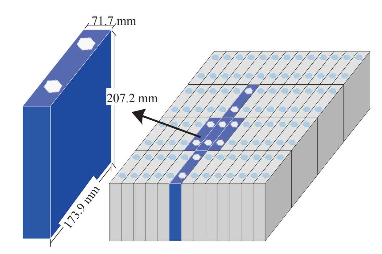
The transition from a single, manageable cell to a complex, high-energy cell energy storage system cabinet exponentially increases safety challenges. The primary failure mechanism leading to fire is thermal runaway. This self-sustaining exothermic reaction can be triggered by several abuse conditions, whose relationships are summarized in the table below:
| Abuse Condition | Mechanism | Consequence & Pathway to Thermal Runaway |
|---|---|---|
| Overcharging | Voltage exceeds design limits, driving undesirable electrolyte decomposition and lithium plating. | Gas generation (e.g., CO, H₂) increases pressure; plating creates dendritic shorts; heat from reactions raises temperature, accelerating further decomposition. |
| Over-discharging | Voltage drops too low, causing copper current collector dissolution and electrode structural damage. | Dissolved copper can redeposit, creating internal shorts upon subsequent charge, leading to localized heating and potential ignition. |
| Internal/External Short Circuit | Direct, low-resistance path between anode and cathode, either from manufacturing defect or physical damage. | Massive current flow generates intense Joule heating (\(Q = I^2R_{short}t\)), rapidly elevating cell temperature beyond critical thresholds. |
| Mechanical Abuse | Crush, penetration, or severe impact deforming the cell structure. | Internal separators are compromised, causing immediate large-scale internal short circuits and localized thermal runaway initiation. |
| Thermal Abuse | External heat source or failure of cooling system raises cell temperature. | Directly heats the cell to the onset temperature where exothermic decomposition reactions begin, initiating the runaway sequence. |
Once initiated, thermal runaway follows a characteristic chain of exothermic reactions. The sequence often begins with the breakdown of the Solid Electrolyte Interphase (SEI) layer (~80-120°C), followed by reactions between the anode and electrolyte, cathode decomposition releasing oxygen, and finally combustion of electrolyte solvents. The total energy released can be catastrophic within the confined space of a cell energy storage system cabinet.
Fire Protection System Design for Cell Energy Storage System Cabinets
The design of a fire protection system for a large-capacity cell energy storage system cabinet must be holistic, integrating prevention, early detection, rapid suppression, and containment. The primary objectives are:
1. Prevention: Maintain optimal operating temperatures through thermal management to prevent conditions conducive to thermal runaway.
2. Early Detection: Identify incipient failure signatures (gas, heat, smoke) before full-scale thermal runaway occurs.
3. Rapid Suppression: Extinguish flames and cool affected cells instantly upon fire ignition to prevent propagation.
4. Containment: Isolate the fire within a single module or cabinet to protect adjacent assets and personnel.
System Components and Requirements
A comprehensive fire protection system comprises several interdependent subsystems.
1. Thermal Management System (Prevention)
This is the first line of defense. An effective cooling system removes generated heat, maintaining cell temperatures within a safe operating window (e.g., 15°C – 35°C). Common methods include:
– Air Cooling: For lower density systems, using fans and ducts. Heat removal capacity is limited by air’s specific heat.
– Liquid Cooling: Essential for high-density cell energy storage system cabinets. Coolant (often a dielectric fluid) circulates through cold plates in direct contact with battery cells. The heat transfer rate is significantly higher. The required cooling power \(P_{cool}\) can be estimated from the system’s inefficiency:
$$P_{cool} \approx \eta_{loss} \cdot P_{op}$$
where \(\eta_{loss}\) is the fractional energy lost as heat during operation and \(P_{op}\) is the operational power.
2. Detection and Early Warning System
Early detection is critical for activating suppression before a single cell failure cascades. A multi-sensor approach is mandatory:
– Battery Management System (BMS) Analytics: Monitors cell voltage, current, and temperature. Advanced algorithms can detect voltage divergence or abnormal temperature rise rates (\(\frac{dT}{dt}\)), indicating potential internal short circuits.
– Gas Detection: Electrolyte decomposition gases (CO, H₂, HF, VOCs) are early indicators of cell venting, occurring before smoke or open flame. Sensors for these gases provide the earliest possible warning.
– Smoke/Aerosol Detection: Very Early Smoke Detection Apparatus (VESDA) or laser-based detectors can sense microscopic particles from overheating components.
– Heat/Flame Detection: Linear heat sensing cables (detecting a specific temperature threshold along their length) and infrared/ultraviolet flame detectors provide confirmation of thermal event progression.
The detection logic should be multi-stage. For example, a combination of gas detection and a localized temperature spike from the BMS might trigger a Level-1 alarm (investigation), while confirmed smoke or flame detection triggers immediate Level-2 alarm and agent release.
3. Automatic Fire Suppression System
This is the reactive core. Upon confirmed fire detection, the system must deploy an extinguishing agent within seconds. The choice of agent is crucial for a cell energy storage system cabinet, as it must be effective on Class A (solid), Class C (electrical), and deep-seated chemical fires. The dominant solutions are clean agent gaseous systems.
| Suppression Agent | Chemical Formula / Type | Mechanism of Action | Key Advantages | Key Considerations |
|---|---|---|---|---|
| FK-5-1-12 (Novec 1230) | C6F12O (Fluorinated Ketone) | Primarily physical: High heat capacity absorbs energy, cooling the fire. Minimal chemical interference. | Excellent environmental profile (low GWP, zero ODP), safe for occupied spaces, non-conductive, leaves no residue. | Requires higher design concentration (~4-6%) compared to some halocarbons. Higher cost per kg. |
| HFC-227ea (FM-200) | C3HF7 (Hydrofluorocarbon) | Chemical and physical: Interrupts the combustion chain reaction while absorbing some heat. | Fast discharge and knockdown, proven history, requires lower design concentration (~7-8%). | Higher Global Warming Potential (GWP) than Novec 1230, though lower than older halons. |
| IG-541 (Inergen) | N2 (52%), Ar (40%), CO2 (8%) | Physical: Reduces oxygen concentration below the level that supports combustion (to ~12-15%). | Completely natural, no environmental impact, safe for electronics (no thermal shock). | Requires large storage cylinders due to low volumetric efficiency, high pressure system. |
| Water Mist / Fine Spray | H2O | Physical: Extreme heat absorption (latent heat of vaporization) cools fuel and surroundings; vapor displaces oxygen. | Abundant, inexpensive, non-toxic, excellent cooling for post-suppression thermal management. | Conducts electricity (risk if cabinets are energized); can cause collateral water damage; requires drainage. |
The required mass of a gaseous agent \(m_{agent}\) for a cabinet volume \(V\) is calculated using the design concentration \(C\) and relevant factors:
$$m_{agent} = \frac{V \cdot C}{1 – C} \cdot \frac{1}{s}$$
where \(s\) is the specific volume of the superheated vapor at the anticipated temperature. For a cell energy storage system cabinet with a net volume of 30 m³ and a design concentration of 6% for Novec 1230, the required agent mass would be substantial, highlighting the need for precise hydraulic calculations.
4. Integration and Containment Architecture
Effective design integrates these subsystems within a physically robust container. Key principles include:
– Compartmentalization: The cell energy storage system cabinet should be divided into individual, sealed modules or racks. Fire-rated barriers (≥1 hour) between modules can contain a fire event.
– Ventilation Control: Normally closed dampers that seal automatically upon detection to create a contained volume for gaseous agent effectiveness and prevent oxygen ingress.
– Agent Delivery: Nozzles must be positioned to ensure uniform flooding of the protected volume, with consideration for cabinet obstructions (battery racks, cables).
– System Interface: The fire protection control panel must integrate seamlessly with the cabinet’s BMS, thermal management controls, and facility emergency systems for coordinated response.
Safety and Performance Assessment
The efficacy of a fire protection system for a cell energy storage system cabinet is quantified through rigorous performance metrics and cost-benefit analysis.
Key Performance Indicators (KPIs):
| KPI Category | Specific Metric | Target / Benchmark | Significance |
|---|---|---|---|
| Detection Performance | Time to Detect Incipient Fault (Gas/Temp) | < 60 seconds | Maximizes window for preventive action or early suppression. |
| Time to Detect Confirmed Fire (Smoke/Flame) | < 10 seconds | Minimizes fire growth before suppression activation. | |
| False Alarm Rate | < 1 per system per year | Ensures system credibility and avoids unnecessary downtime/discharge. | |
| Suppression Performance | Agent Discharge Time (for gaseous systems) | < 10 seconds | Rapid knock-down of flame to prevent propagation. |
| Design Concentration Hold Time | > 10 minutes | Prevents re-ignition from hot surfaces during the cooling phase. | |
| Post-Discharge Cooling Capacity | Able to reduce hotspot temp below 80°C | Mitigates thermal runaway propagation from adjacent cells. | |
| System Reliability | Probability of Failure on Demand (PFD) | < 0.01 (SIL 2 equivalent) | Quantifies the likelihood the system will fail to operate when needed. |
Cost-Benefit Analysis:
Justifying the investment in an advanced fire protection system requires analyzing both tangible and intangible costs against potential losses.
– Capital Costs: Include detectors, control panels, suppression agent, cylinders/pipework, installation, and design engineering. For a large cell energy storage system cabinet, this can range from 10% to 20% of the total cabinet cost, with gaseous systems being a significant portion.
– Operational Costs: Include periodic inspection, testing, maintenance, and agent recharge/replacement.
– Benefit (Risk Mitigation): The primary benefit is the avoidance of catastrophic loss. The potential loss \(L_{event}\) from an unprotected fire includes:
$$L_{event} = C_{asset} + C_{downtime} + C_{cleanup} + C_{reputation} + C_{regulatory}$$
where \(C_{asset}\) is the total value of the destroyed cell energy storage system and cabinet, \(C_{downtime}\) is lost revenue from system unavailability, \(C_{cleanup}\) includes hazardous material disposal, \(C_{reputation}\) is brand damage, and \(C_{regulatory}\) encompasses fines and increased insurance premiums. A robust fire protection system drastically reduces the probability of such an event, transforming a high-consequence, low-probability risk into a manageable one.
Future developments in fire protection for cell energy storage systems are leaning towards greater intelligence and integration. Research is focused on:
1. Predictive Analytics: Using machine learning on BMS and sensor data to predict cell failure days or weeks in advance, allowing for preventative maintenance.
2. Agent Optimization: Developing “smart” suppression systems that can adjust agent type or quantity based on real-time fire characterization.
3. Material Science: Integrating flame-retardant or intumescent materials directly into cell components, module housings, and pack structures to slow fire spread at the source.
4. Standardization: Evolving industry standards (e.g., NFPA 855, UL 9540A) to provide clearer, performance-based testing and design guidelines for fire safety in cell energy storage system cabinets.
In conclusion, securing a large-capacity cell energy storage system cabinet demands a multi-layered, defense-in-depth strategy. This strategy seamlessly integrates proactive thermal management, multi-spectrum early detection, rapid and appropriate suppression, and physical containment. The fire protection system is not an optional add-on but a fundamental engineering requirement that safeguards significant capital investment, ensures grid reliability, and protects personnel and surrounding infrastructure. As energy storage densities increase and deployments scale, continued innovation and rigorous application of these fire safety principles will be essential for the sustainable and safe growth of the global energy storage ecosystem.