
In recent years, with the intensification of global climate change, China’s energy structure has also been constantly changing, and wind power generation, as a renewable energy source, has been vigorously developed. But the randomness, intermittency, and uncertainty of wind power bring more and more challenges to the safety of the power grid. Energy storage systems, with their ability to absorb and release electrical energy in a short period of time, have become an effective means of suppressing the output power of new energy and improving the grid’s ability to accept new energy generation.
According to type classification, energy storage is generally divided into energy type and power type. Energy based energy storage has a short cycle life and relatively low response speed, but has a high energy density, mainly including battery energy storage, fuel cells, etc; On the contrary, the power type energy storage cycle has a longer lifespan and faster response speed, but its capacity is relatively low, mainly including supercapacitors, flywheel energy storage, etc. Combining the characteristics of two types of energy storage, this article adopts a hybrid energy storage system that combines energy type lithium-ion batteries and power type flywheels to suppress the fluctuation of wind power output power, thereby increasing the utilization rate of the energy storage system and reducing the required capacity of the energy storage system.
Domestic and foreign scholars have conducted relevant research on how to develop effective control strategies and reasonably configure the capacity of energy storage devices for hybrid energy storage systems composed of energy and power based energy storage based on their own characteristics. Introducing state of charge (SOC) feedback to optimize power allocation based on the use of second-order low-pass filters; The method of adaptive variational mode decomposition can effectively solve the problem of frequency band aliasing in empirical mode decomposition (EMD), but in practice, sufficient length of data needs to be obtained to decompose more effectively and accurately; Adopting model predictive control, utilizing its characteristics of early prediction and priority control, effectively solves the problem of excessive flattening during the energy storage compensation process; Based on batteries and supercapacitors, wavelet packet decomposition is used to suppress wind power output fluctuations; The introduction of energy storage SOC fuzzy control based on wavelet packet decomposition optimizes the working state of energy storage. However, the wavelet packet decomposition method usually uses 0 nodes as the reference power for grid connection of the power generation system. The problem of large frequency band spans between different decomposition layers will lead to excessive allocation of energy storage capacity and excessive suppression of the output power of the power generation system. Moreover, for power allocation between different types of energy storage arrays in hybrid energy storage systems, the response time of different energy storage arrays is usually only used as a reference, and the advantages of various types of energy storage arrays cannot be fully utilized.
In response to the problems in the above research, a hybrid energy storage system composed of flywheel and lithium-ion battery energy storage array is adopted to suppress the active power output of the wind farm. Firstly, the overall structure of the hybrid energy storage system connected to the wind farm is introduced, and a 250 kW/50 kWh flywheel energy storage unit model and a 250 kW/150 kWh lithium-ion battery energy storage unit model are established to compare their dynamic performance. Then, under the constraint of the “Technical Regulations for Connecting Wind Farm to Power System”, an improved wavelet packet decomposition method using multi frequency signals as the reference power for wind power grid connection is proposed to obtain the overall charging and discharging instructions of the hybrid energy storage array. Next, based on the boundary time of the charging and discharging response between lithium-ion batteries and flywheel energy storage, as well as the energy distribution of each node after improved wavelet packet decomposition, a charging and discharging instruction allocation method for the flywheel and lithium-ion battery energy storage array is obtained. Based on the probability distribution characteristics of the charging and discharging instructions of the flywheel and lithium-ion battery energy storage array, a probability density function is used for fitting, and a certain confidence level confidence interval is set to limit it. Considering the charging and discharging efficiency and state of charge of the energy storage array, a measurement factor is introduced to optimize the number of selected flywheel energy storage units, and a hybrid energy storage system capacity configuration method is proposed, Increase the utilization rate of energy storage systems and reduce the required capacity of energy storage systems. Finally, combined with the energy storage unit model and historical operating data of wind farms, the capacity configuration method and suppression effect of the hybrid energy storage system are simulated and verified.
1.Characteristic analysis of hybrid energy storage system
As shown in Figure 1, the hybrid energy storage system connects nf flywheel energy storage units with nb lithium-ion battery energy storage units through a DC/AC converter in parallel with an AC bus, forming a flywheel and lithium-ion battery energy storage array.
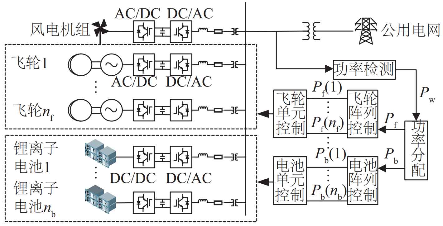
This access method can obtain modular large energy storage units, and the energy storage is relatively independent of the wind turbine, without causing significant interference to the control of the wind turbine itself. During operation, the output power pw of the wind farm is obtained through the power distribution controller of the hybrid energy storage system to obtain the charging and discharging instructions pf and pb for the flywheel and lithium-ion battery energy storage array. Then, after passing through the flywheel array and lithium-ion battery controller, the charging and discharging instructions [pf (1),…, pf (d),…, p (f nf)], [pb (1),…, pb (m),…, pb (nb)] for the flywheel energy storage unit and lithium-ion battery energy storage unit are obtained, The flywheel energy storage unit compensates for the output power of the lithium-ion battery energy storage unit [pfess (1),…, pfess (d),…, pfes (s nf)], [pb (at 1),…, pb (at m),…, pb (at nb)].
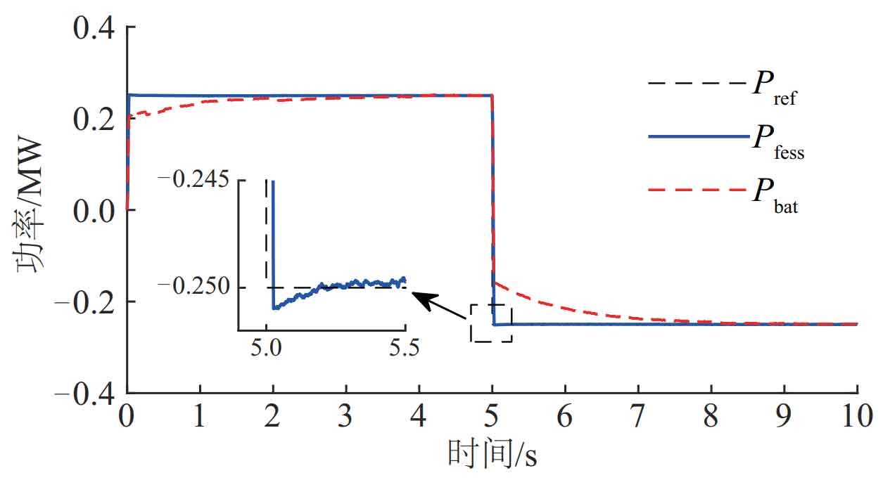
Referring to the parameters of energy storage units in relevant literature, establish models of 250 kW/50 kWh flywheel energy storage and 250 kW/150 kWh lithium-ion battery energy storage units. As shown in Figure 2, within 1 second and 2 seconds, the output power pr (ef d) of the d-th flywheel energy storage unit and the output power pb (at m) of the m-th lithium-ion battery energy storage unit can quickly and accurately follow the reference power pre f. The response speed of the flywheel is significantly higher than that of the lithium-ion battery, which is consistent with its own characteristics. To obtain the energy storage system power and electricity required to suppress power fluctuations in wind farms, each energy storage unit can be combined into an array.
| Installed capacity of wind farm/MW | 1 minute maximum change/MW | 10 min maximum change/MW |
| <30 | 3 | 10 |
| 30-150 | Installed capacity/10 | Installed capacity/3 |
| 150 | 15 | 50 |
The current standard for regulating wind power fluctuations is based on the “Technical Regulations for Wind Farm Connection to the Power System” (GB/T 19963.1-2021), which limits the maximum change in wind power grid connected power within 1 minute and 10 minutes to not exceed 1/10 and 1/3 of the installed capacity of the wind farm. As shown in Table 1, this is the control objective for suppressing power fluctuations in wind power grid connection, and based on this, reasonable control strategies are designed to reduce the capacity configuration of hybrid energy storage systems.
2.Capacity Configuration Method for Hybrid Energy Storage Systems
2.1 Improved wavelet packet decomposition method
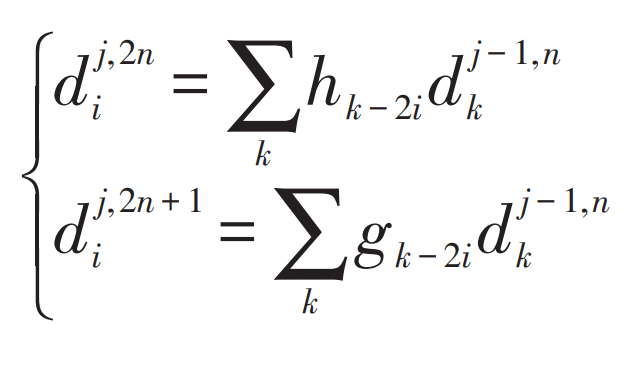
Based on the theories of wavelet analysis and multi resolution analysis, wavelet packet decomposition performs finer division on the basis of wavelet decomposition, decomposing both high and low frequency signals to obtain a complete binary tree structure. The basic decomposition and reconstruction algorithms are:
Decomposition algorithm:
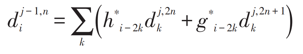
Reconstruction algorithm:
In the formula: d j, 2ni, d j, 2n+1i – wavelet packet decomposition coefficient; Hk-2i, gk-2i – wavelets
Low pass and high pass filter banks for packet decomposition; H * i-2k, g * i-2k – low-pass and high-pass filter banks reconstructed from wavelet packets.
As shown in Figure 3, existing studies usually use the P (j, 0) node as the reference power for wind farm grid connection. However, wavelet packet decomposition uses a binary division method for each node. If P (j, 0) is directly taken as the grid connection reference power, when the number of decomposition layers is small, the frequency difference between it and the adjacent layer P (j+1, 0) nodes is too large, which will result in a significant difference in the required energy storage capacity configuration. At this time, if P (j -1, 0) node is taken as the wind farm grid connection reference power, it cannot meet the grid connection standards.
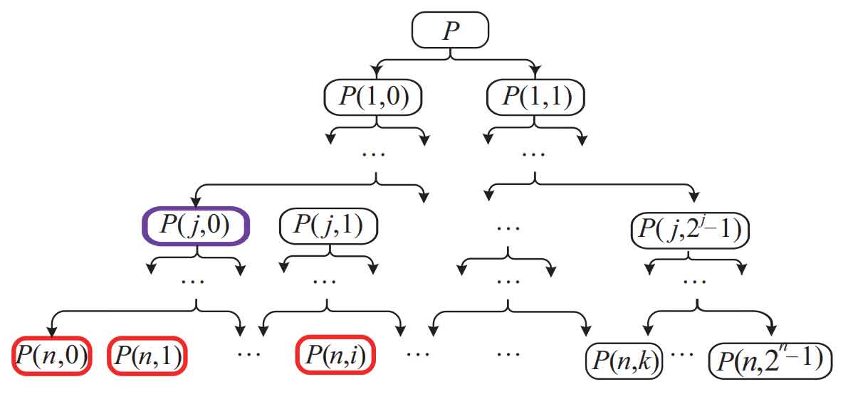
In response to the above issues, this article proposes an improved wavelet packet decomposition method: using multi node P (n, 0: i), (i=11/42n-1) as the reference power for wind farm grid connection, as shown in Figure 3. This can increase the number of decomposition layers of wavelet packets and more finely divide the wind power frequency band. Then, stack the horizontal nodes to determine if they exceed the limits of the grid connection standard for flat wind power.
2.2 Power allocation methods for different types of energy storage arrays
After determining the decomposition layers of wavelet packets and the reference power of wind farm grid connection, the overall power required for compensation of the hybrid energy storage array is obtained. In response to the characteristics of high energy density, slow response speed, and short cycle life of lithium-ion battery energy storage arrays, as well as the characteristics of fast response speed, long cycle life, but low energy density of flywheel energy storage arrays, the boundary point k between secondary and high frequency power is determined to obtain different types of charging and discharging instruction allocation methods for energy storage arrays.
2.2.1 First selection of k value
According to the literature, the response time of lithium-ion batteries is usually between seconds and hours, and the response time of flywheel energy storage is usually between milliseconds and tens of minutes. As the charging and discharging frequency of the battery increases, the battery life will decrease. In this article, we will choose within 100 seconds as the boundary time for lithium-ion batteries and flywheel energy storage charging and discharging response, corresponding to a frequency of 0.01 Hz, which is similar to the frequency of node P (n, d), From this, k ≤ d is obtained.
2.2.2 Second selection of k value
By calculating the wavelet packet energy spectrum function of the power allocated to each node of the energy storage array, the energy distribution ratio of each node in P (n, i+1:2n-1) is obtained, and the secondary selection of k value is carried out. The basic principle is to select the node with a sharp decrease in energy as the k value, provided that k is not greater than d, in order to avoid increasing the number of charging and discharging switching times for lithium-ion batteries due to less energy, This results in a decrease in its cyclic service life. By selecting k values, different types of energy storage array power allocation methods are obtained.
2.3 Capacity configuration method for hybrid energy storage systems
The capacity of a hybrid energy storage system is the sum of the capacity of the flywheel and lithium-ion battery energy storage array. The charging and discharging instructions obtained through the power distribution controller of the hybrid energy storage system are considered as the rated power of the flywheel energy storage array and the lithium-ion battery energy storage array. Taking into account the charging and discharging efficiency and SOC of the energy storage array, the formula for calculating the charging and discharging demand of the energy storage array is:
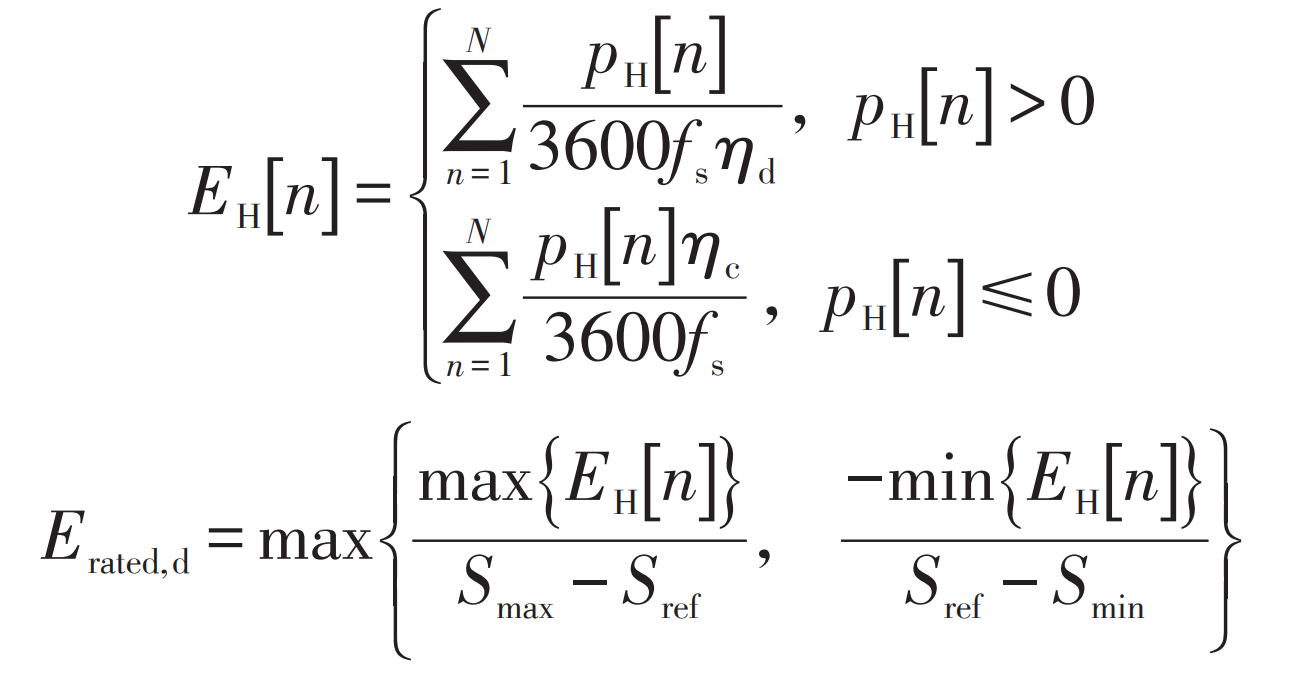
In the formula: n=[1,2,…, N], where N is the number of sampled data; PH [n] – Charging and discharging power of energy storage array; η D – discharge efficiency; η C – Charging efficiency; Smax, Smin – upper and lower limits of SOC for energy storage arrays; Fs – sampling frequency; Sref – Initial SOC of energy storage array; Erated, d – The configured energy storage array’s power level.
According to the analysis in section 2.1, the larger n, the better the filtering and smoothing effect, but the more energy storage units are required. However, in the process of energy storage compensation, after wavelet packet decomposition of power allocation, there will be some large values of allocated power, which will lead to a significant increase in the capacity configuration of the energy storage array. Multiple functions are used to fit the probability density of charging and discharging instructions for each energy storage array. After comparing the fitting degrees of different functions, the probability density function with the highest fitting degree is selected, Then determine the confidence interval at a certain level of confidence and limit the charging and discharging instructions of the energy storage array.
The limiting conditions for setting the capacity of the energy storage array are as follows:
1) The capacity configuration of a hybrid energy storage system composed of a flywheel array and a lithium-ion battery array should be 20% lower than the installed capacity of the wind farm.
2) The rated capacity of the flywheel array should avoid appearing near integer multiples of the flywheel energy storage unit.
Introducing measurement factors in the calculation process ζ , As shown in equation (5).
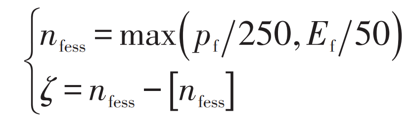
In the formula: [nfess] – Round down; ζ ∈[ According to equation (5), it can be seen that, ζ It can reflect the size of the backup capacity of the configured flywheel energy storage system, ζ Being too small will result in a smaller flywheel array configuration requirement and increase the number of flywheel energy storage units, ζ The excessive meeting resulted in the reserve capacity of the energy storage system being too small. This study considers that the reserve capacity range of the flywheel energy storage system is within [50225] kW, which is set to ζ The range of values is [0.2, 0.9]. By selecting a confidence level, limit the charging and discharging instructions for energy storage.
3.Example analysis
Selecting typical 24-hour data from a wind farm with an installed capacity of 15 MW in a certain region as the research object, the power output during this time period is shown in the PW curve in Figure 4. The maximum value is 15 MW, the minimum value is 0.49 MW, the average value is 5.4 MW, and the maximum changes in active power output in 1 minute and 10 minutes are 5.72 MW and 10.24 MW, respectively. This does not comply with the regulations for wind farms to connect to the power system and is not conducive to the large-scale grid connection of the power grid, Therefore, it is necessary to smooth the wind power output and improve the quality of grid connection.
Firstly, based on the DB6 wavelet, the initial values n=4 and i=4 are set. According to the process, the optimal decomposition level of the wavelet packet is determined to be 5, and the final value of i is 5, that is, P (5,0:5) is used as the reference power for wind power grid connection.
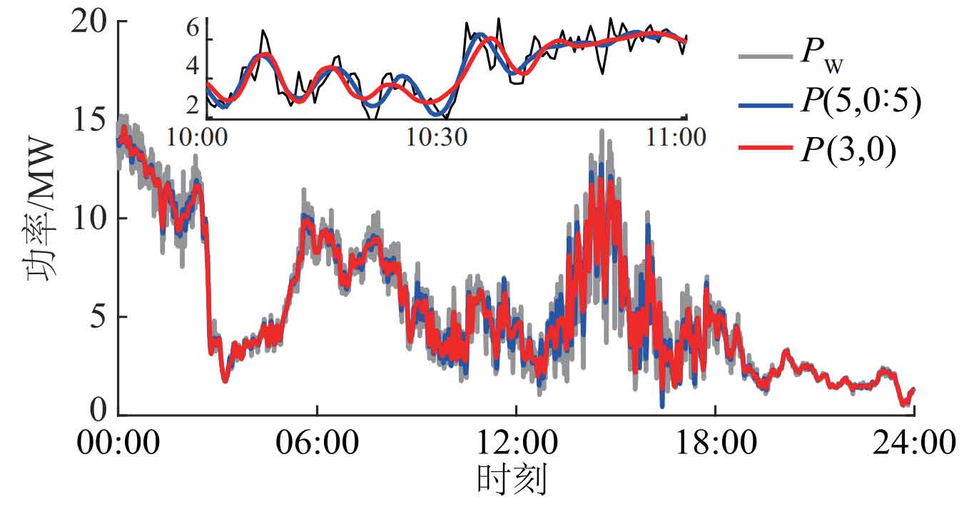
As shown in Figure 5, using the existing wavelet packet decomposition method [9], the maximum changes in active power output of wind power grid connection reference curves obtained based on the P (3,0) node at 1 minute and 10 minutes are 1.61 MW and 6.50 MW, respectively. This excessively suppresses the output power of wind power generation, resulting in a required energy storage capacity of up to 4.5017 MW.
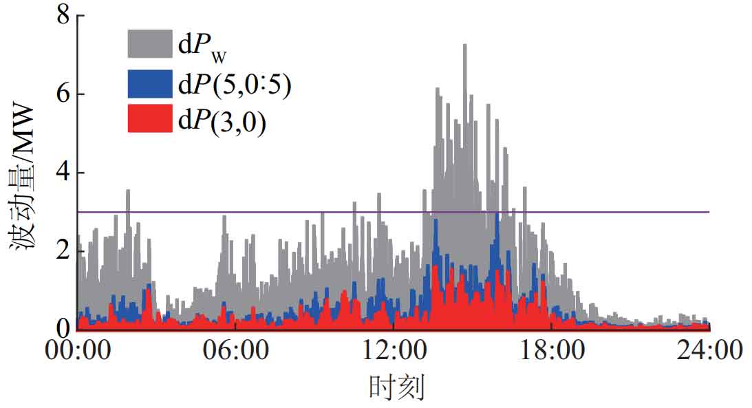
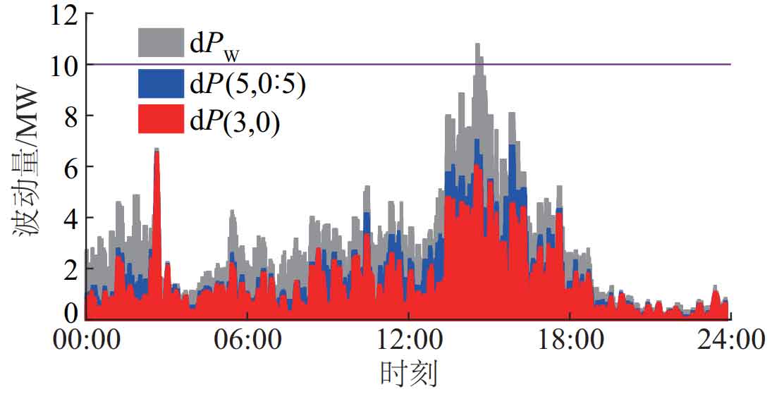
By using an improved wavelet packet decomposition method, the maximum changes in the active power output of the wind power grid connection reference curves after P (5,0:5) multi node flattening at 1 minute and 10 minutes are 2.25 MW and 7.67 MW, respectively. This meets the grid connection standards of wind farms and requires a minimum energy storage capacity of 3.5098 MW. Compared to the existing wavelet packet decomposition method, the required energy storage system capacity is reduced by 22.03%.
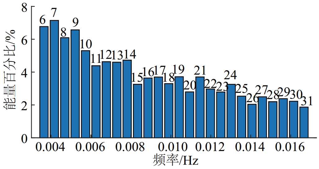
As shown in Figure 6, the response frequency of 0.01 Hz is similar to that of node 18 in the wavelet packet decomposition frequency band. Based on the energy distribution ratio of each node, it can be seen that among all nodes before node 18, the energy distribution ratio of node 15 has significantly decreased, and subsequent nodes have not significantly increased, showing an overall downward trend. According to the analysis in section 2.2, node 15 is used as the boundary node for lithium-ion battery energy storage and flywheel energy storage array charging and discharging instructions, that is, P (5,6:14) multi nodes are used as the reference power curve of lithium-ion battery energy storage array, and P (5,15:31) multi nodes are used as the reference power curve of flywheel energy storage array. At this time, the number of charging and discharging switching times of lithium-ion battery energy storage array is 799 times/d. The charging and discharging command allocation method only considers the charging and discharging response time of lithium-ion batteries and flywheel energy storage, with a charging and discharging switching frequency of 864 times per day for lithium-ion batteries. Therefore, the method proposed in this article reduces the number of charge and discharge switching times for lithium-ion battery energy storage arrays by 7.52%. Under this setting, the maximum charge and discharge power allocated to the lithium-ion battery energy storage array is -3.30 MW and 3.19 MW, respectively; The maximum charging and discharging power allocated to the flywheel array is -2.34 MW and 2.09 MW, respectively, indicating that the total capacity configuration of the hybrid energy storage system is at least 5.64 MW. 13 250 kW/150 kWh lithium-ion battery energy storage units and 10 250 kW/50 kWh flywheel energy storage units are required.
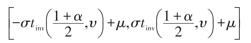
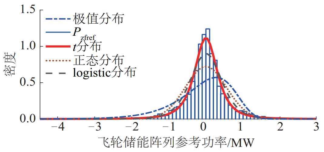
As shown in Figure 7, taking the flywheel energy storage array as an example, the probability density Pzfref curve of the flywheel array charge and discharge instructions shows that the larger part of the flywheel array charge and discharge instructions has a very small probability density, but this value leads to a sharp increase in the configuration of the flywheel array. As shown in Figure 7, using different functions to fit the reference power of the energy storage array, it can be seen that the t-distribution fitting result is closer to the distribution of the reference power of the flywheel energy storage array. Calculate the confidence intervals at different confidence levels in the t-distribution fitting curve, limit the reference power of the energy storage array, and no longer compensate for reference power values with low probability of occurrence. The expression for the confidence interval is:
Due to the selection of a certain confidence level to limit the reference power of the energy storage array, it is no longer necessary to compensate for some power values with larger reference power, which will inevitably lead to the fluctuation of wind farm grid connected power exceeding the grid connection standard in a short period of time. However, according to the Technical Regulations for Wind Farm Connection to the Power System, it is acceptable to accept situations where the maximum change rate is exceeded due to a decrease in wind speed. The fluctuation of wind speed usually follows the Weibull distribution, and its confidence interval is selected at a 95% confidence level as the normal variation interval of wind speed, which requires that the output power fluctuation of the wind farm should not exceed the grid connection standard for more than 72 minutes during the 24-hour working time. In order to demonstrate the effectiveness of the hybrid energy storage system in suppressing wind power fluctuations, this article sets a limit threshold of 5 minutes, and the capacity configuration of the hybrid energy storage system should be 20% lower than the installed capacity of the wind farm, in order to determine α The value of.
Under different confidence levels, the rated power and capacity of lithium-ion battery energy storage arrays and flywheel energy storage arrays are shown in Table 2. Erate, zb, Erate, zf represent the rated capacity of lithium-ion battery energy storage arrays and flywheel energy storage arrays, nt represents the time when the wind farm grid connected power fluctuation exceeds the limit, and L represents the maximum fluctuation rate of grid connected reference power. It can be seen that as the confidence level continues to decrease, the capacity of the hybrid energy storage system is also significantly reduced, but its fluctuation rate and the time of fluctuation exceeding the limit are also increasing. When choosing a confidence level of 97%, a 1.33 MW/0.4398 MWh lithium-ion battery energy storage array and a 0.94 MW/0.2239 MWh flywheel energy storage array need to be configured, which exceed the fluctuation limit for only 1.5 minutes, meeting the fluctuation exceeding time limit (<5 minutes). If a confidence level of 98% is selected, the capacity of the hybrid energy storage system will increase, and the time beyond the fluctuation limit will be reduced to 0.5 minutes. If the confidence level is chosen to be 96%, the limit on the time for fluctuations to exceed the limit cannot be met. Therefore, in this example, the final confidence level was determined to be 97%. Again ζ Perform calculations to obtain ζ = 0.47 ∈ [0.2, 0.9]. The total capacity configuration of the optimized hybrid energy storage system (2.27 MW) has decreased by 59.75% compared to before (5.64 MW), and meets the limit of fluctuation time. Therefore, a hybrid energy storage system consisting of six 250 kW/150 kWh lithium-ion battery energy storage units and five 250 kW/50 kWh flywheel energy storage units is selected to suppress fluctuations in wind farm output power.
| α/% | Pzbref /MW | Pzfref /MW | Erate,zb /MWh | Erate,zf /MWh | nt | L/% |
| 80 | 0.50 | 0.39 | 0.2942 | 0.1230 | 17 | 39.56 |
| 85 | 0.61 | 0.47 | 0.3072 | 0.2221 | 15 | 37.48 |
| 90 | 0.78 | 0.59 | 0.3845 | 0.2823 | 12 | 35.37 |
| 95 | 1.06 | 0.80 | 0.4261 | 0.2769 | 6 | 31.68 |
| 96 | 1.22 | 0.89 | 0.4386 | 0.2056 | 5 | 29.61 |
| 97 | 1.33 | 0.94 | 0.4398 | 0.2239 | 1.5 | 28.10 |
| 98 | 1.57 | 1.09 | 0.4462 | 0.2548 | 0.5 | 24.29 |
| 99 | 1.85 | 1.30 | 0.4524 | 0.2659 | 0.5 | 21.23 |
By combining the energy storage unit model and the energy storage array control strategy with equal time allocation, the discharge depths of the flywheel energy storage unit and the lithium-ion battery energy storage unit are set to be 15%~85% and 5%~95%, respectively. The initial SOC is 70% and 50%, respectively. The discharge efficiency is 95% and 90%, and the charging efficiency is 95% and 90%, respectively. Establish a hybrid energy storage system composed of a flywheel and lithium-ion battery energy storage array to suppress the output power of the wind farm.
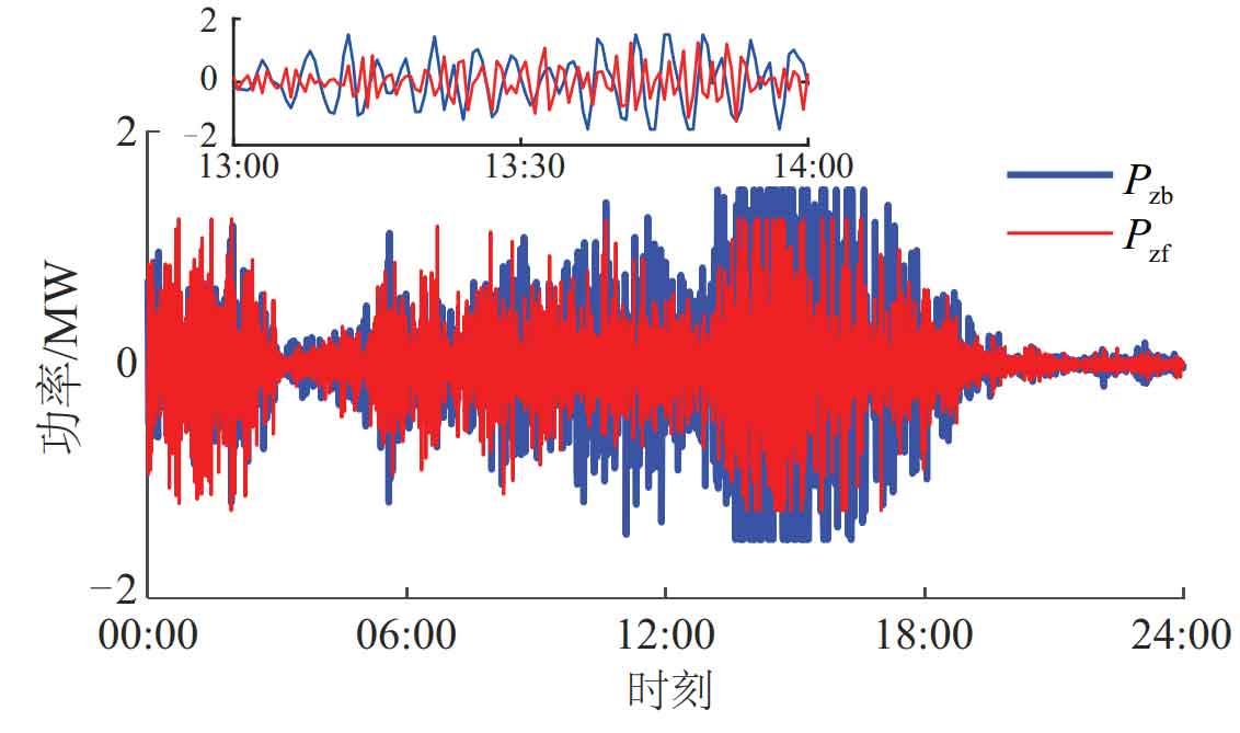
The output power Pzb of lithium-ion batteries and the output power Pzf of flywheel energy storage arrays are shown in Figure 8. It can be seen that lithium-ion battery energy storage arrays compensate for larger amplitude and lower frequency power components compared to flywheel energy storage arrays.
The changes in SOC of the energy storage array are shown in Figure 9, and due to energy loss, its overall trend is decreasing. During this process, the state of charge (eSOCzb) of the lithium-ion battery energy storage array varies between 34.02% and 51.10%, while the state of charge (eSOCzf) of the flywheel energy storage array varies between 20.84% and 73.08%, indicating the rationality of the proposed hybrid energy storage system capacity configuration method.
4.Conclusion
This article adopts a hybrid energy storage system composed of a flywheel and a lithium-ion battery energy storage array to suppress the fluctuation of wind farm output power. The innovation points and main work of this article are as follows:
1) According to the Technical Regulations on the Integration of Wind Farm into Power System, an improved wavelet packet decomposition method using multiple nodes as the reference power for wind farm grid connection is proposed to address the issue of large frequency band spans between different decomposition layers in wavelet packet decomposition. The charging and discharging instructions of the hybrid energy storage system are obtained. Compared with existing wavelet packet decomposition methods, the required capacity of the hybrid energy storage system is reduced by 22.03%.
2) Based on the response time of different types of energy storage arrays and the improved wavelet packet decomposition of the energy distribution of each node after wind farm output power, a charging and discharging instruction allocation method for different types of energy storage arrays is proposed. Compared to the charging and discharging command allocation method based solely on the charging and discharging response time of lithium-ion batteries and flywheel energy storage arrays, the charging and discharging switching times of lithium-ion battery energy storage arrays are reduced by 7.52%.
3) Based on the probability distribution characteristics of the charging and discharging instructions mentioned above, a probability distribution function is used for fitting, and the confidence interval at a certain confidence level is limited. A measurement factor is introduced for correction, and a hybrid energy storage system capacity configuration method is proposed. Apply the t-distribution function to fit the probability density distribution of the charging and discharging power of each energy storage array, and set a confidence interval at a 97% confidence level to limit the charging and discharging instructions of each energy storage array, so that the flattened grid connected power of the wind farm meets the Technical Regulations for Wind Farm Connection to the Power System. The capacity configuration of the hybrid energy storage system has decreased by 59.75% compared to before, thereby increasing the utilization rate of the hybrid energy storage system and reducing its required capacity.