
In the transition toward a low‑carbon energy future, new energy generation technologies such as wind and solar power have been widely deployed. However, their inherent intermittency and spatial imbalance pose significant challenges to grid stability and power quality. Battery energy storage systems (BESS) have emerged as a critical enabler to address these issues by converting and storing electrical energy in various forms, thereby smoothing fluctuations, providing backup power, and enhancing overall system efficiency. In this paper, we present a comprehensive analysis of the application and optimization of battery energy storage systems in new energy generation systems, drawing on the latest technological advances and practical deployment experiences. We focus on the technical characteristics, matching scenarios, and profit optimization strategies of BESS, aiming to form a power grid that balances efficiency, safety, greenness, and economy.
The rapid growth of renewable energy installations demands large‑scale energy storage solutions. Battery energy storage systems, particularly electrochemical batteries such as lithium‑ion, sodium‑ion, flow batteries, and supercapacitors, have become the backbone of modern energy storage. Unlike traditional pumped‑hydro storage, BESS offer modularity, fast response, and scalability, making them suitable for a wide range of applications from distributed generation to utility‑scale storage. The following sections detail the current state of BESS technologies, their matching application scenarios, and optimization strategies to maximize their value in new energy generation systems.
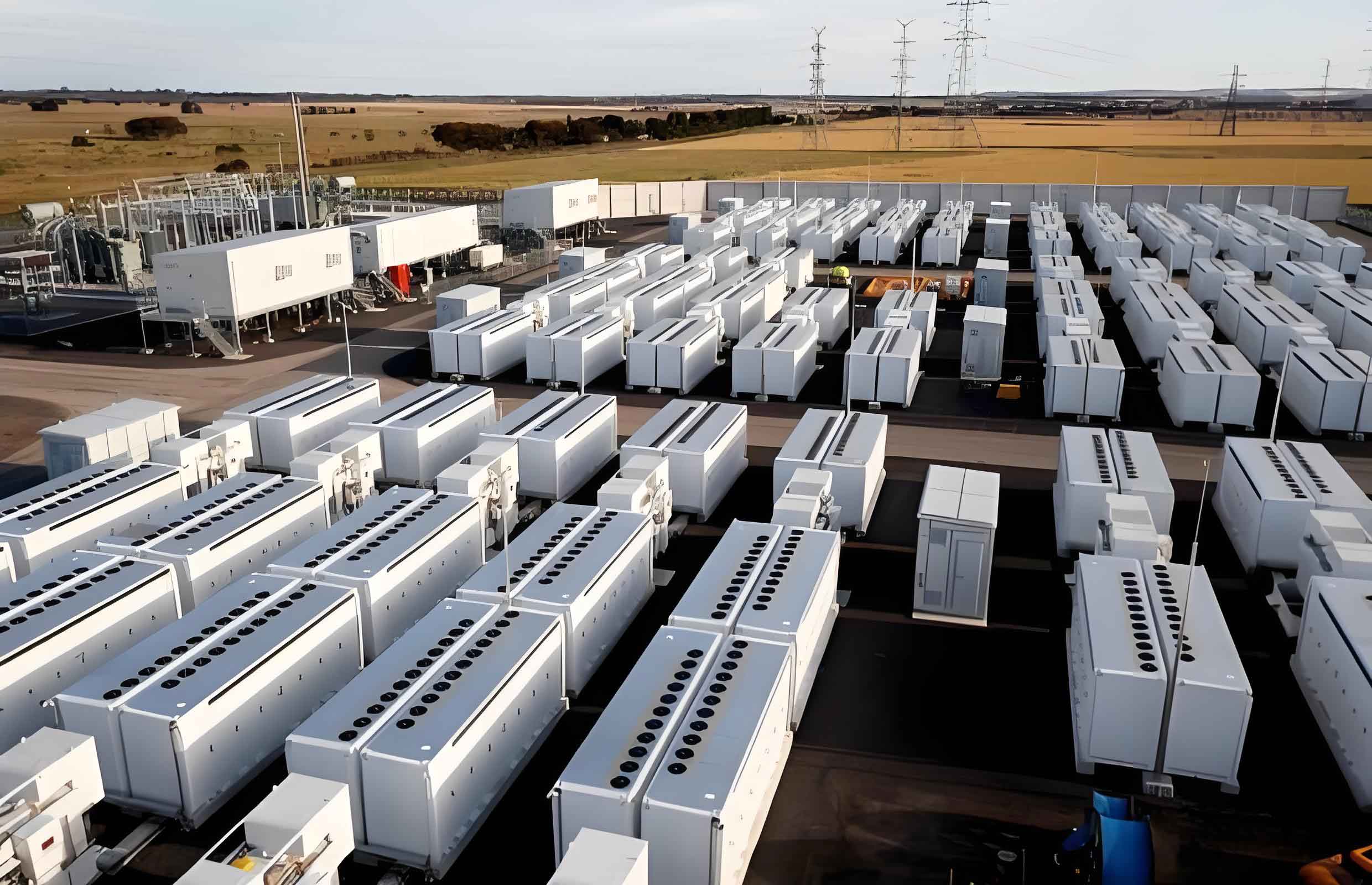
1. Current Status of Battery Energy Storage Systems Technologies
Battery energy storage systems encompass a diverse set of electrochemical technologies, each with distinct characteristics that determine their suitability for different applications. The most mature technology is lithium‑ion batteries, which have seen rapid cost reductions and performance improvements over the past decade. Lithium‑iron‑phosphate (LFP) and ternary lithium‑ion batteries dominate the market due to their high energy density, long cycle life, and high round‑trip efficiency. Recent innovations include ceramic‑coated wet‑separator technology that enhances thermal stability and puncture resistance, reducing the risk of internal short circuits caused by lithium dendrite growth. For lithium extraction, processes such as low‑grade brine extraction with advanced lithium adsorbents and phase‑change materials have been developed to improve purity and reduce environmental impact.
Beyond lithium‑ion, sodium‑ion batteries are gaining attention due to the abundance and low cost of sodium. Technologies such as sodium‑sulfur (NaS), sodium‑salt (NaAlCl₄), and sodium‑air batteries have been developed, with sodium‑sulfur batteries already deployed in large‑scale stationary storage. The polyanion‑type sodium‑iron‑sulfate battery offers an open framework that provides spacious sodium‑ion diffusion channels, significantly extending cycle life. Prussian blue analogues are still under research, focusing on controlling crystallization water and vacancies to stabilize electrochemical performance. Meanwhile, flow batteries (e.g., vanadium redox flow batteries) provide decoupled power and energy capacities, allowing deep discharge without damaging the battery, making them ideal for long‑duration storage applications. Supercapacitors, though not strictly batteries, are often integrated into BESS for high‑power applications such as frequency regulation and smoothing renewable energy fluctuations.
To compare these technologies, we present Table 1 summarizing key performance parameters and typical applications.
| Technology | Energy Density (Wh/kg) | Cycle Life (cycles) | Round‑trip Efficiency (%) | Response Time | Maturity | Typical Applications |
|---|---|---|---|---|---|---|
| Lithium‑ion (LFP) | 120–160 | 4000–8000 | 90–95 | ms | Commercial | Utility storage, EVs, grid support |
| Lithium‑ion (NMC) | 200–250 | 2000–4000 | 92–96 | ms | Commercial | Electric vehicles, portable devices |
| Sodium‑sulfur (NaS) | 150–240 | 2500–4500 | 85–90 | s | Commercial | Large‑scale stationary storage, load leveling |
| Sodium‑ion (Prussian blue) | 100–160 | 1000–3000 | 80–88 | ms | R&D | Grid storage, low‑cost applications |
| Vanadium redox flow | 15–25 (system) | 10,000+ | 75–82 | s | Commercial | Long‑duration storage, renewable integration |
| Supercapacitor | 5–10 | 500,000+ | 95+ | ms | Commercial | Frequency regulation, power quality |
From Table 1, it is evident that no single chemistry dominates all scenarios. For applications requiring high energy density and fast response, lithium‑ion remains the workhorse. For ultra‑long cycle life and deep discharge, flow batteries are preferred. The choice of battery energy storage systems must be tailored to the specific operational requirements of the new energy generation system.
2. Application Scenarios of Battery Energy Storage Systems in New Energy Generation
Battery energy storage systems serve critical functions across the entire power system: generation side, transmission and distribution side, and consumption side. On the generation side, BESS are deployed next to wind farms or solar parks to mitigate output variability. As the share of renewable generation increases, these storage systems provide essential services such as peak shaving, frequency regulation, and black‑start capability. For example, a 100 MW wind farm may be paired with a 20‑30 MWh lithium‑ion BESS to smooth power fluctuations and meet grid code requirements.
On the transmission and distribution side, BESS can defer infrastructure upgrades, provide voltage support, and enhance system reliability. In urban areas, distributed battery energy storage systems can be aggregated to provide virtual power plant services. On the consumption side, behind‑the‑meter BESS allow commercial and residential users to store excess solar PV generation for later use, reducing electricity bills through time‑of‑use arbitrage.
Table 2 summarizes the main application scenarios and the corresponding BESS requirements.
| Application | Location | Typical Power (MW) | Duration Required | Key BESS Feature |
|---|---|---|---|---|
| Renewable smoothing (wind/solar) | Generation side | 10–200 | 0.5–4 h | Fast response, long cycle life |
| Frequency regulation | Grid side | 1–50 | 15 min–1 h | High power, fast ramp rate |
| Peak shaving | Generation/transmission | 10–500 | 2–8 h | High energy capacity, low cost per kWh |
| Black‑start | Generation side | 1–20 | 0.5–2 h | Reliable startup, voltage control |
| Time‑of‑use arbitrage | Consumer side | 0.1–5 | 2–6 h | Moderate power, high efficiency |
| Backup power | Consumer side | 0.01–1 | 1–4 h | Low self‑discharge, safety |
To quantify the performance of battery energy storage systems in these applications, we define several key metrics. The round‑trip efficiency η is given by:
$$ \eta = \frac{E_{\text{discharge}}}{E_{\text{charge}}} \times 100\% $$
where E₍discharge₎ and E₍charge₎ are the total energy discharged and charged over a cycle, respectively. For a BESS providing frequency regulation, the power ramp rate R (MW/s) is crucial:
$$ R = \frac{\Delta P}{\Delta t} $$
where ΔP is the change in power output over time interval Δt. Battery energy storage systems with high R values (e.g., supercapacitors or lithium‑ion) are preferred for fast regulation services.
3. Optimization Strategies for Battery Energy Storage Systems in New Energy Generation
To maximize the economic and technical benefits of battery energy storage systems, we propose a set of optimization strategies covering compensation mechanisms, grid integration, and management coverage.
3.1. Independent Storage Compensation Mechanism
In many new energy generation systems, BESS operate independently from the primary generation units, acting as a compensation module that absorbs excess energy during low‑demand periods and releases it during shortages or voltage dips. This design requires a dedicated control system that can respond to real‑time grid conditions. We advocate for establishing a compensation mechanism that includes both energy‑type (capacity) and power‑type (ramp) services. The profitability of such a system can be modeled by the following objective function for daily operation:
$$ \max \sum_{t=1}^{T} \left[ \lambda_t^{\text{discharge}} P_t^{\text{discharge}} \Delta t – \lambda_t^{\text{charge}} P_t^{\text{charge}} \Delta t – C_{\text{deg}}(E_t) \right] $$
subject to:
$$ 0 \leq P_t^{\text{charge}} \leq P_{\text{max}}^{\text{charge}}, \quad 0 \leq P_t^{\text{discharge}} \leq P_{\text{max}}^{\text{discharge}} $$
$$ \text{SOC}_{t+1} = \text{SOC}_t + \eta_{\text{charge}} \frac{P_t^{\text{charge}} \Delta t}{E_{\text{rated}}} – \frac{P_t^{\text{discharge}} \Delta t}{\eta_{\text{discharge}} E_{\text{rated}}} $$
$$ \text{SOC}_{\text{min}} \leq \text{SOC}_t \leq \text{SOC}_{\text{max}} $$
Here, λₜ represents the electricity price at time t, P is power, Δt is the time step, C₍deg₎ models battery degradation costs as a function of energy throughput Eₜ, and SOC is the state of charge. This optimization can be solved using mixed‑integer linear programming or dynamic programming to determine the optimal charging/discharging schedule. Real‑world implementations require accurate forecasting of renewable generation and load, as well as market prices.
Table 3 provides a summary of key parameter values used in typical optimization models for battery energy storage systems.
| Parameter | Symbol | Unit | Typical Value (Lithium‑ion) |
|---|---|---|---|
| Maximum charge power | P₍max₎^charge | MW | 0.5 × E₍rated₎ per hour |
| Maximum discharge power | P₍max₎^discharge | MW | 0.5 × E₍rated₎ per hour |
| Round‑trip efficiency | η | % | 92 |
| Minimum SOC | SOC₍min₎ | % | 10 |
| Maximum SOC | SOC₍max₎ | % | 90 |
| Degradation cost coefficient | C₍deg₎ | $/MWh | 5–15 |
3.2. Enhanced Grid Integration and Coordination
Battery energy storage systems must be seamlessly integrated into the grid to exchange power with users and other sources. This requires robust communication protocols, standardized interfaces, and coordinated control with other grid assets. We emphasize the need for a hierarchical control framework that combines local battery management systems (BMS) with a central energy management system (EMS). The EMS can dispatch multiple battery energy storage systems to provide aggregated services such as frequency regulation or congestion relief. The coordination problem can be formulated as a multi‑agent optimization where each BESS agent maximizes its own profit while satisfying global constraints. For instance, the total power output from a cluster of N BESS must meet a requested regulation signal P₍req₎(t):
$$ \sum_{i=1}^{N} P_i(t) = P_{\text{req}}(t) $$
Additionally, we must consider grid voltage and frequency constraints. The voltage stability at a bus can be expressed using the power flow equation:
$$ V_k = V_k^{\text{ref}} – \sum_{j} (R_{kj} P_j + X_{kj} Q_j) / V_k $$
where Vₖ is the voltage magnitude at bus k, Rₖⱼ and Xₖⱼ are the line resistance and reactance, and Pⱼ, Qⱼ are active and reactive power injections. Battery energy storage systems with four‑quadrant power converters can provide both active and reactive power support, thus improving voltage profiles. Optimization strategies that incorporate such grid constraints are essential for large‑scale deployment of battery energy storage systems.
3.3. Expanded Management Coverage through Smart Monitoring
As the scale of battery energy storage systems grows, it becomes imperative to expand their management coverage to ensure safety and longevity. We propose a multi‑layer monitoring framework that includes cell‑level voltage/temperature sensing, module‑level current/state‑of‑health estimation, and system‑level performance analytics. Advanced data‑driven techniques, such as machine learning, can be used to predict capacity fade and detect anomalies. For example, the remaining useful life (RUL) of a lithium‑ion cell can be estimated using a linear regression model with features extracted from cycling data:
$$ \text{RUL} = a_0 + a_1 \cdot N_{\text{cycles}} + a_2 \cdot \text{SOH}_{\text{init}} + a_3 \cdot T_{\text{avg}} $$
where N₍cycles₎ is the number of completed cycles, SOH₍init₎ is the initial state of health, and T₍avg₎ is the average temperature during operation. Historical data from similar battery energy storage systems can be used to train the model. Additionally, digital twin technology can create a virtual replica of the physical BESS, enabling real‑time simulation and predictive maintenance. Table 4 lists the key parameters monitored in modern battery energy storage systems.
| Parameter | Unit | Sensor Type | Impact on Performance |
|---|---|---|---|
| Cell voltage | V | Voltage sensor | Over‑voltage/under‑voltage protection |
| Cell temperature | °C | Thermocouple, NTC | Degradation rate, thermal runaway |
| Current | A | Hall effect sensor | State of charge, health |
| State of charge (SOC) | % | Kalman filter estimation | Available energy, depth of discharge |
| State of health (SOH) | % | Capacity test, impedance | Remaining useful life |
| Internal resistance | mΩ | AC impedance spectroscopy | Power capability, aging |
By integrating these data streams into a central cloud platform, operators can schedule maintenance proactively, optimize thermal management, and balance cell usage to extend the lifetime of battery energy storage systems. This approach aligns with the principle of “prevention first, control assurance” and ensures safe operation under diverse and sometimes harsh environmental conditions.
4. Conclusion
Battery energy storage systems have become an indispensable component of modern new energy generation systems. Through our analysis, we have demonstrated that the selection of appropriate BESS technologies must be matched to specific application scenarios—capacity‑type batteries for peak shaving and renewable smoothing, and power‑type batteries for frequency regulation and fast response. The optimization of battery energy storage systems requires a holistic approach: establishing independent storage compensation mechanisms with a clear economic model, enhancing grid integration through coordinated control and standardized protocols, and expanding management coverage with intelligent monitoring and predictive analytics. The formulas and tables presented in this paper provide a quantitative framework for designing and operating battery energy storage systems in new energy generation. As technology continues to advance—particularly in lithium‑ion, sodium‑ion, and flow battery chemistries—the performance and cost‑effectiveness of BESS will further improve, accelerating the transition to a low‑carbon, reliable, and efficient power system.