
1. Structure of photovoltaic cells
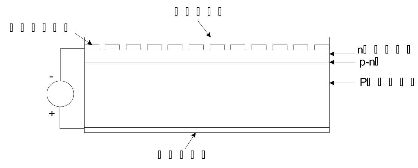
Regarding the structure of photovoltaic cells, we can analyze it based on the structure of crystalline silicon solar cells, as shown in Figure 1.The crystalline silicon solar cell uses silicon semiconductor materials as raw materials, and forms a special thin layer at the junction through P-type and N-type materials. The PN junction is the potential difference of this thin layer. When light is irradiated on the wafer, the holes in the N region move toward the P region, and electrons move from P to N, thus creating a potential difference in the PN junction.Usually, the structure of N+/P homojunction is used, which is a layer of heavily doped N-type layer with a thickness of ~0.3 µm on a p-type silicon wafer (thickness of about 500 µm) with an area of about 10 cm×10 cm. The semiconductor has poor conductivity, and it cannot be coated with a metal that hinders the absorption of sunlight on the surface.Therefore, it is necessary to fabricate metal gate lines on the N-type layer, which is the front contact electrode.Then, metal films are also fabricated on the entire back surface as the back ohmic contact electrode.This forms a crystalline silicon solar cell.Because the surface of silicon is too smooth, the sunlight irradiated on the surface will be reflected, which will waste a lot of sunlight. Therefore, we can cover the entire surface with an anti-reflective film, which can reduce the reflection loss of light.
2. Power generation principle and characterization parameters of photovoltaic cells
Solar cells, also known as photovoltaic cells, are a device that converts solar radiation directly into electrical energy.This device is packaged into solar cell modules, and then assembled into solar cell arrays using one or more modules as needed to achieve a certain power. By matching and combining with energy storage devices, measurement and control devices, and DC-AC conversion devices, various devices perform their respective functions, but none of them is dispensable. They together form a solar cell power generation system, also known as a photovoltaic power generation system.The solar power generation system described in this chapter refers to the direct conversion of solar energy into electrical energy for industrial and domestic power supply.This method is generally referred to as direct conversion power supply, which is a new energy source. This energy source is different from other energy sources in that it does not consume conventional energy sources. Because there are no rotating parts, it is very easy to maintain, easy to operate in the work, no noise, and does not cause environmental pollution.The most important thing is that its service life is relatively long.
2.1 Principle of photovoltaic cell
As we all know, semiconductors are materials with electrical conductivity, with a resistivity between that of conductors and insulators, and a relatively weak electrical conductivity. Moreover, the electrical conductivity of semiconductors is also affected by external factors.Solar cells are made using the properties of semiconductors.When illuminated, the cells generate electromotive force, thereby obtaining energy.Solar cell power generation is mainly based on the photovoltaic effect, which is the phenomenon of generating potential differences between uneven semiconductors or between different parts of a semiconductor and a metal by irradiating light.The formation of voltage by photovoltaic effect is an energy conversion process, in which the light energy obtained through illumination is converted into electrical energy through internal structural transformation, and the movement of charges generates electromotive force.With the generation of voltage, coupled with the connection of the two, a current loop is formed.
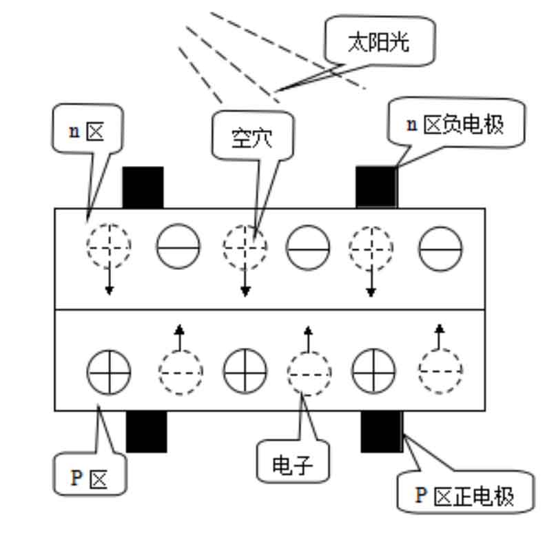
When sunlight shines on the PN junction of the photovoltaic cell surface, if the energy of the incident photons is greater than the band gap of the semiconductor material, the absorption of photons in the N region, P region, and junction region will produce electron-hole pairs.As long as a few carriers are closer to the PN junction than their diffusion length, there is always a chance of diffusion to the junction interface.A space charge region (depletion region) will appear at the junction region where the interface between the N region and the P region.In this region, an electric field will be formed between the positive and negative charges, and the direction of the electric field is from the N region to the P region. This electric field is called the built-in electric field.Those few carriers (holes) that diffuse to the junction interface are pulled to the P region by the built-in electric field.Similarly, if a few carriers (electrons) generated in the P region near the junction diffuse to the junction interface, they will also be pulled to the N region by the built-in electric field, and the generated electron-hole pairs will move to the N region and P region respectively under the action of the built-in electric field.If the external circuit is open, these photoelectrons and holes accumulate near the PN junction, causing the P region to acquire additional positive charges and the N region to acquire additional negative charges, resulting in a photovoltaic potential generated at the PN junction.If the external circuit is connected to a load and is in a state of conduction, the photovoltaic potential generated by the PN junction begins to supply power, generating a current flowing from the P region and into the N region, thus driving the load to work.
2.2 Characterization parameters of solar cells
The working principle of solar cells mainly stems from the photovoltaic effect. Under the characteristic action of PN junction diodes, there is a diode current ID flowing from the p-region to the n-region. When sunlight shines on the solar cell, a photocurrent Iph will be generated, flowing from the n-region to the p-region, which is exactly opposite to ID. In fact, the resulting current I is:
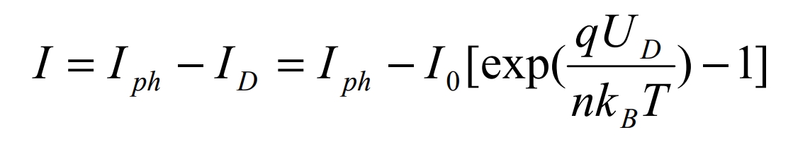
In this formula, the proportional coefficient is determined according to the structure and material properties of the solar cell. UD – junction voltage, I0 – diode reverse saturation current, Iph – photocurrent proportional to the intensity of incident light, n – ideal coefficient (n value), which is a characteristic parameter of the PN junction (1-2), q – electron charge, KB – Boltzmann constant, T – temperature.
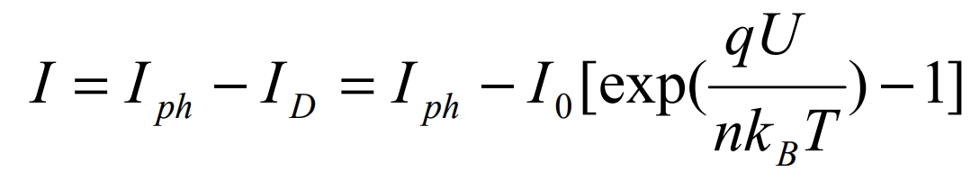
If the series resistance RS of the solar cell is neglected, UD is the terminal voltage of the solar cell, and the formula can be written as:
When the output end of the solar cell is short-circuited, U=0 (UD≈0), the short-circuit current can be obtained from the formula:
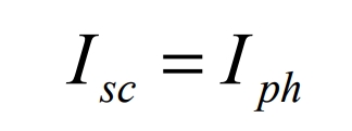
That is, the short-circuit current of solar cells is proportional to the intensity of incident light and equal to the photocurrent.
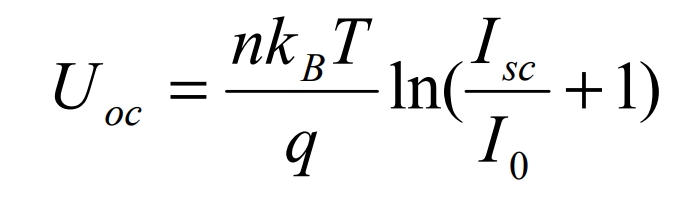
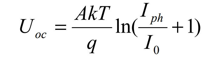
When the output terminal of the solar cell is open-circuited, I = 0, and the open-circuit voltage can be obtained from the formula:
The solar cell is connected to a load R that can vary from zero to infinity. When the load Rm maximizes the output power of the solar cell, its corresponding maximum power Pm is:
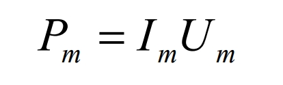
where mI and Um represent the optimal operating current and voltage, respectively.The ratio of the product of Uoc and scI to the maximum power pm is defined as the fill factor FF, which is given by:
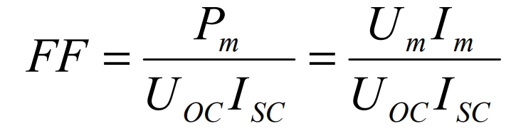
The important characteristic parameter of solar cells is the fill factor FF, which increases as the output power increases.
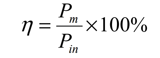
The conversion efficiency of solar cells is the ratio of the maximum output power of solar cells to the total radiant energy Pin irradiated on solar cells, that is:
3. Equivalent circuit of solar cell
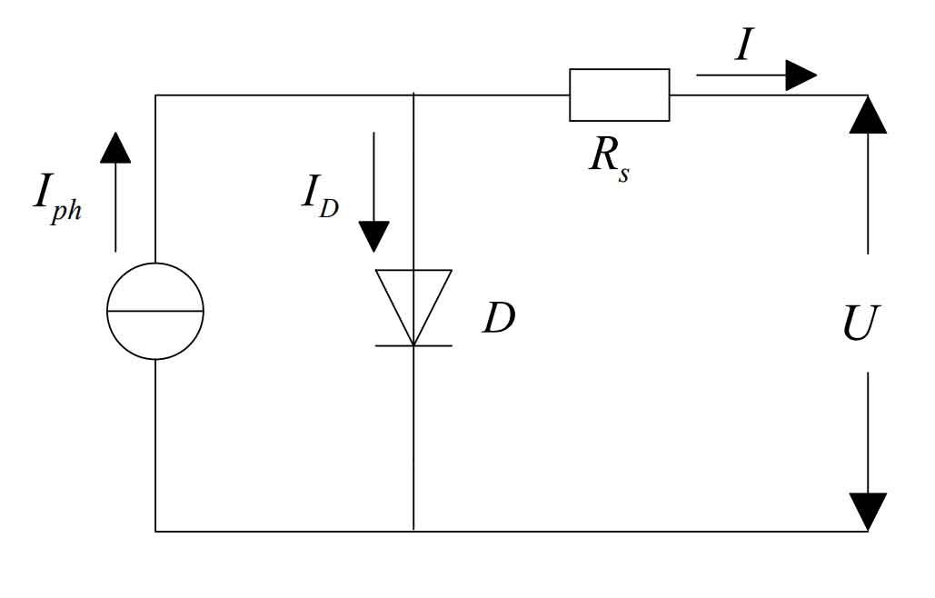
The working basis of solar cells is the photovoltaic effect, and its equivalent circuit diagram is as follows:

In the figure, Rs – series resistance, generally less than 1Ω, is the equivalent resistance when considering lateral current.Rsh – shunt resistance (parallel resistance), generally thousands of ohms, mainly due to leakage current sh I caused by PN junction defects.DI – dark current, a unidirectional current, occurs under the condition of no illumination, and is generated by the PN junction under the action of external voltage.Its size can indicate the change of total diffusion current of photovoltaic cells at current temperature.From the equivalent circuit diagram, the relationship between current and voltage at both ends of solar cells can be obtained as follows:
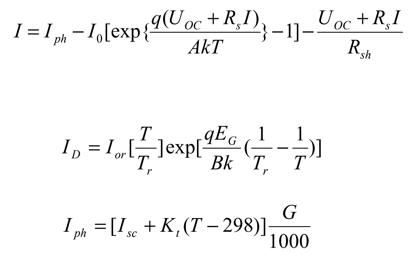
The parameters in the formula are analyzed in the table.
| Parameter Name | Definition | Numerical value |
| I | Output current of photovoltaic cells | variable |
| Uoc | Output voltage of photovoltaic cells | variable |
| 0 I | Reverse saturation current of photovoltaic cells | constant |
| PH I | Photogenerated current | variable |
| Or I | Diode reverse saturation current | constant |
| Sc I | Short circuit current under standard test conditions | constant |
| T | Photovoltaic cell temperature | constant |
| G | Sunlight intensity | variable |
| A. B | Ideal factor | Between 1 and 2 |
| K | Boltzmann constant | Constant 23 1.38 10/J K − × |
| Q | Electronic power | Constant 19 1.6 10 C − × |
| EG | Bandgap width of semiconductor materials | constant |
| Kt | Short circuit current temperature coefficient | constant |
| Tr | Reference temperature | 298K |
The change in series resistance Rs does not affect the open-circuit voltage, but the short-circuit current decreases as Rs increases.Similarly, the change in parallel resistance only affects the open-circuit voltage, which decreases as Rsh increases, but has little effect on the short-circuit current.If solar cells want to achieve higher output power, they need to minimize the series resistance Rs and increase the parallel resistance Rsh.Because the parallel resistance Rsh is very large and can be neglected, the simplified equivalent circuit of the solar cell is:
It can be seen from the simplified equivalent circuit diagram.
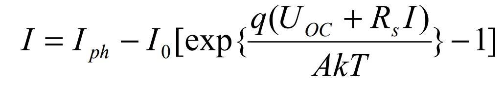
When short-circuited, Uoc = 0, the photovoltaic current ph I flows entirely to the external short-circuit load, and the short-circuit current sc I is almost equal to the photocurrent, with ph sc I = I. When open-circuited, ph sc I = I, and the photocurrent flows entirely through the diode D, at which point the open-circuit voltage is:
It is not difficult to see from the above formula that external factors such as temperature and sunshine intensity affect the output current and voltage of photovoltaic cells.Different external conditions will result in different short-circuit currents sc I. The same is true for open-circuit voltage, and their relationship can be expressed as:
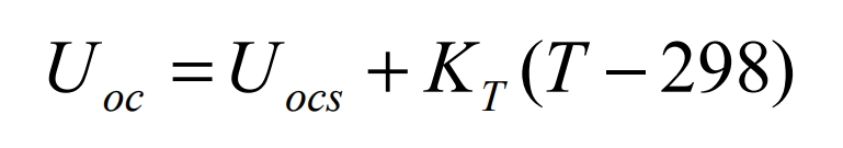
Where, Uocs is the open-circuit voltage under standard test conditions (temperature of 25℃, sunshine intensity of 21000W/m2), and KT is the temperature coefficient of the open-circuit voltage.
4. Photovoltaic cell array
Many individual photovoltaic cells are combined in series and parallel to form a photovoltaic cell array.The output DC current of a solar power generation system can be significantly increased by parallel connection of photovoltaic cells, while the output DC voltage can be increased when they are connected in series.In summary, we can obtain the desired output DC voltage or current by changing the combination of photovoltaic cells, that is, changing the series and parallel connection of cells.The circuit structure of a photovoltaic cell array is shown in Figure 5:
As shown in the figure above, the anti-reverse flow diode is a component that can be placed inside the controller. It can prevent current from accidentally entering the battery or other solar cell circuits in the component.
Bypass diode: It can reduce the damage caused by the thermal spot effect of the component due to shadowing.Its limitation is that it must meet the requirement that its reverse voltage is more than 1.5 times the maximum output voltage of the protected battery string.
The phenomenon of local heating points on components under the influence of sunlight is known as thermal spot effect.This phenomenon usually occurs on individual cells.If affected by external factors, some things block the light, forming a shadow on some of the battery cells in the component. The shadowed cells lose power and become loads due to the loss of light, and the resistance also increases.At this time, the increased resistance causes all the voltage in the series circuit to be applied to this cell. Due to the high temperature generated by the current flowing through the high resistance cell, the surrounding materials expand, discolor, and the solder joints melt.Severe thermal spot effect may cause hundreds of degrees Celsius of high temperature, which can cause more serious consequences and even burn the battery.To avoid the above situation, it is necessary to install bypass diodes.
At this time, the output characteristic equation of the photovoltaic cell array is:
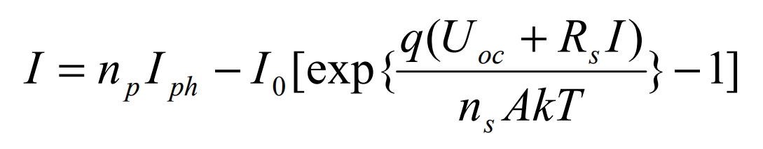
Where, np and ns are the number of photovoltaic cells in parallel and in series in the array, respectively.
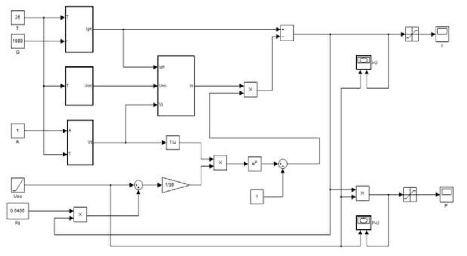
5. Photovoltaic Cell Simulation Based on SIMULINK
Through the analysis and modeling of photovoltaic cells described above, we used Matlab to simulate photovoltaic cells. The simulation module is shown in the following figure:

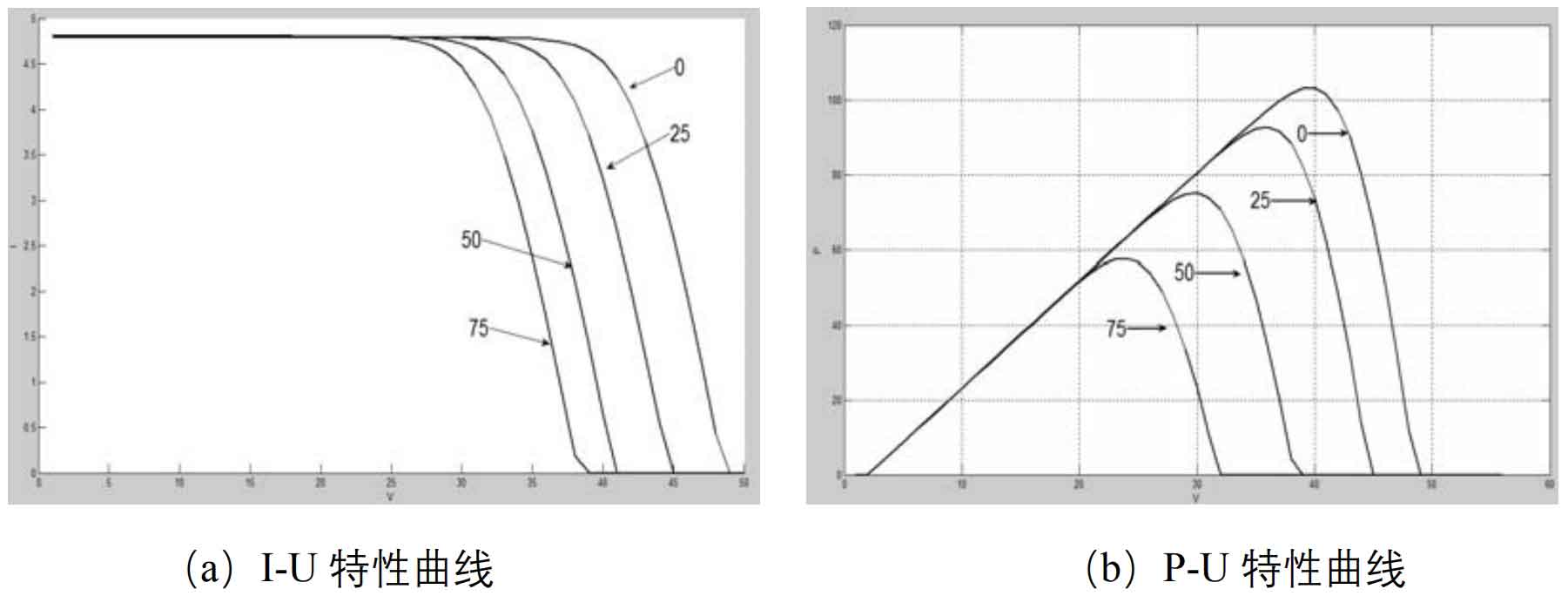
Figure 6 is a Simulink-based simulation model of a photovoltaic array. Figure 7 is the output I-U characteristic curve of the photovoltaic array obtained from the simulation. Figure 8 is the output P-U characteristic curve of the photovoltaic array obtained from the simulation.Figure 9 is the output I-U and P-U characteristic curves of photovoltaic cells under different temperatures and the same light intensity. This graph shows that under the same light intensity, setting different temperatures will affect the open circuit voltage, which will decrease with the increase of temperature. However, the short circuit current is not greatly affected by temperature changes, and it slightly increases with the increase of short circuit current.Overall, the increase of temperature will decrease the output power of photovoltaic cells.
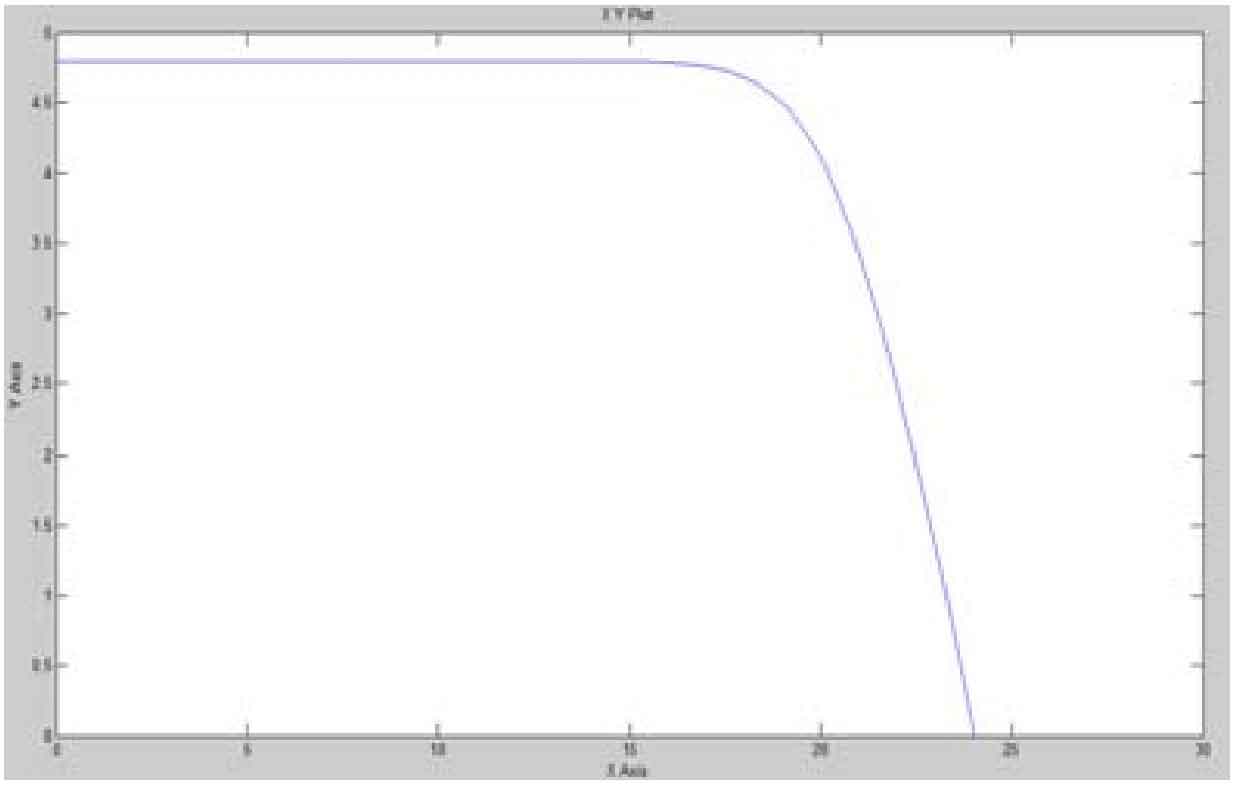
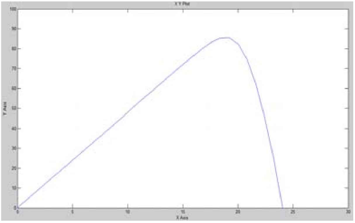
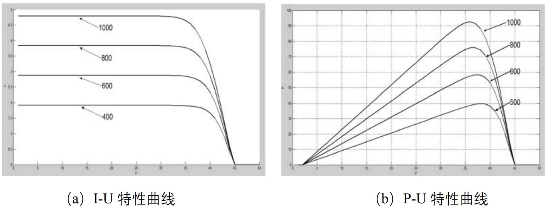
Figure 10 shows the I-U and P-U characteristic output curves of photovoltaic cells under the same temperature and different light intensities. This graph indicates that under the condition of fixed temperature, the short-circuit current of photovoltaic cells will increase with the increase of light intensity.However, the open-circuit voltage of photovoltaic cells is not affected significantly, and there is no obvious change. The open-circuit voltage increases slightly with the increase of light intensity.Overall, the output current value of photovoltaic cells varies greatly with the increase of light intensity, and the output power of photovoltaic cells decreases with the decrease of light intensity.
6. Summary
This chapter first analyzes the working principle and equivalent circuit of photovoltaic cells, gives the physical expression of their electrical characteristics, presents their equivalent circuit, and simplifies it. It also gives the output characteristic equation of photovoltaic cell arrays.We build photovoltaic modules and perform MPPT simulations to analyze the working characteristics of photovoltaic cells. By changing the sunshine intensity and ambient temperature, we compare the different effects of the two on the working characteristic curve of photovoltaic cells.