
The distributed balanced charging structure adds balancing function on the basis of distributed charging. Therefore, the distributed balanced charging system of series energy storage power sources mainly includes three aspects: lower level unit balancing topology, distributed charging system structure, and balancing control strategy. The following will introduce these three aspects separately.
Balanced topology of lower level units in a distributed balanced charging system with series connected energy storage power sources
Battery balancing technology is widely used domestically and internationally to drive new energy vehicles, electric buses, and drones that require high battery voltage. It has a significant promoting effect on solving the problems of low available capacity and reduced cycle life of lithium-ion battery packs caused by the inconsistency of long chain battery cells. Therefore, domestic and foreign scholars have done a lot of work on the research of this technology, and to a certain extent, a complete structural system has already been established.
Its working principle is mainly to use a balancing circuit to charge and discharge individual imbalanced cells, ensuring that the state of charge of the imbalanced cells remains consistent, thereby achieving the purpose of energy transfer, compensating for the differences caused by battery inconsistency, and improving the performance of the battery pack.
At present, battery balancing topology is mainly divided into passive balancing and active balancing according to different forms of energy transformation. Compared to the two, passive equalization circuits were the earliest used equalization circuits and have been widely used in low-power circuits due to their simple structure and control [16]. The structure of an active balancing circuit is more complex than that of a passive balancing circuit, and it also requires corresponding balancing strategies to achieve good balancing effects. However, this circuit does not achieve balancing in the form of energy consumption, but rather achieves balancing through energy transfer between batteries, with higher efficiency and faster balancing speed. It can be applied in high-power circuits.
1. Passive balancing topology
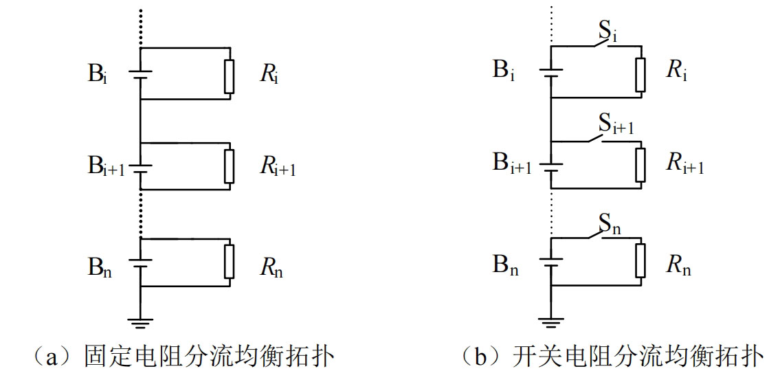
Passive balancing topology belongs to passive balancing circuits, which use heat dissipation to level the battery with higher power and the battery with the lowest power, achieving consistency among the individual cells of the battery pack. The shunt resistor balance structure is more widely used in practice, and can be divided into fixed resistor shunt balance topology and switch resistor shunt balance topology. The fixed resistor shunt balance topology is shown in Figure 1 (a), where each battery is connected in parallel with a resistor through wires to achieve the purpose of shunt. This circuit has a simple structure, low cost, and strong reliability, but due to the limitation of releasing a large amount of heat during charging and discharging, it can only be applied to low-power situations. The switch resistor shunt balance topology is shown in Figure 1 (b). On the basis of a fixed resistor shunt balance topology, a switch element is connected in series between the battery cell and the resistor to selectively discharge the high charge battery. During the battery charging process, the blocking of the switch does not allow each resistor to merge into the circuit, reducing energy loss, Therefore, this circuit structure is more efficient and reliable than a fixed resistor shunt balanced topology.
2. Active balancing topology
Active balancing topology, also known as active balancing circuit, is proposed based on the limitations of passive balancing topology. Active balancing circuits use power electronics technology to balance the energy of high-energy and low-energy batteries, unlike passive balancing topologies that consume excess energy from high-energy batteries. However, the process of balancing energy requires an intermediate energy storage power supply component as a relay, such as an inductor, capacitor, or transformer. From this, it can be seen that the main losses of active balancing topology are only the losses of intermediate energy storage power supply components and the switching losses of switching tubes. Therefore, balancing current can be designed to be large, balancing efficiency and balancing speed can be greatly improved, and it is widely used in high-power applications.
In recent years, more and more scholars have conducted research on active balancing topologies. Active balancing topologies can be divided into four types based on the medium of energy propagation: capacitive, single inductor, multi inductor, and coupled inductor; According to the propagation path of energy, it can be divided into direct equilibrium type and non direct equilibrium type. The following introduction will be conducted from the perspective of energy propagation path.
1.1 Non direct equilibrium
Non direct equilibrium topology refers to the inability to directly transfer energy between any two individual cells or groups within a long chain battery pack. Based on this characteristic, the following introduces three typical inductor equilibrium topologies, taking individual cells, individual cells, and group groups as examples.
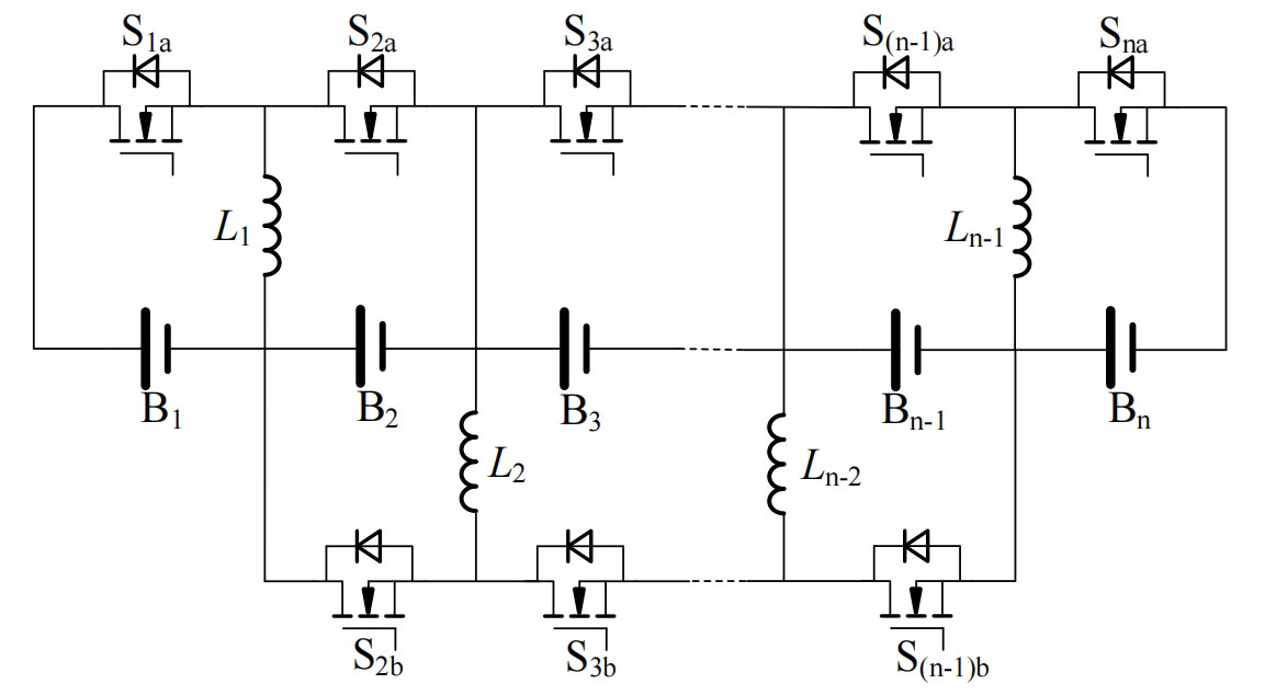
The traditional inductive equalization circuit shown in Figure 2 is an adjacent single to single direct equalization circuit, where each inductor storing energy corresponds to a battery cell and two MOS transistors. When two adjacent batteries are imbalanced, the buck boost mode energy transfer can be achieved by controlling the on/off of MOSFETs. Multiple adjacent batteries can work in parallel simultaneously, which is beneficial for improving the balancing speed. However, when there are non adjacent unbalanced batteries, energy transfer in one cycle needs to be completed through multiple balancing actions, and the balancing efficiency decreases geometrically with the number of balancing steps. Especially when balancing is carried out at the beginning and end of a long chain battery pack, the efficiency is the lowest and the balancing time is the longest. Therefore, this circuit topology has significant limitations in terms of balancing performance.
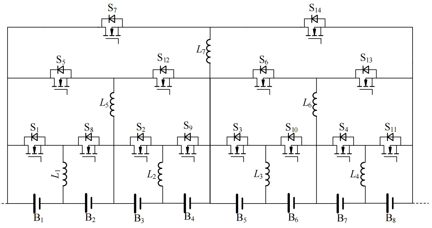
Improvements have been made to this, as shown in Figure 3, which is an improved inductive buck boost equalization circuit. This circuit overcomes the problem of energy transfer from traditional buck boost equalization circuits to individual units, and adds a direct equalization path for some group pairs, making the equalization speed of intermediate units as fast as that of head and tail units. However, the equalization mode of this structure is still not flexible enough, Still unable to achieve direct balancing of any individual cell within the battery pack.
The coupled inductance balanced topology is a balanced circuit with a coupled transformer as the intermediate energy storage power supply component. It generally transfers energy by operating the circuit in flyback mode. There are many types of coupled transformers, including one-to-one coupling, one to many coupling, and many to many coupling. The balancing current of the coupled inductor type balancing circuit is relatively large, so the balancing speed is fast, and energy is transmitted through magnetic isolation, which can transfer energy over long distances, reduce energy loss caused by multi-step balancing, and improve balancing efficiency. However, due to the relatively large volume of coupling transformers, especially in one to many coupled and many to many coupled transformer structures, there may be difficulties in designing coupling transformers due to the large number of coil turns and small magnetic core window area, as well as high PCB layout requirements, which are not easy to expand.
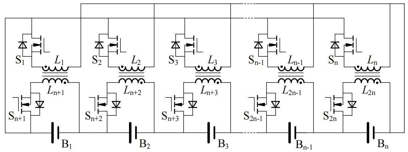
Figure 4 shows a bidirectional coupling balanced circuit [32], in which each battery cell is equipped with a one-to-one coupling transformer and two MOS transistors, which can enable bidirectional energy transfer between the battery pack and cells. However, this circuit has serious balancing overlap, which can lead to high loss, long balancing time, and other problems. It also cannot achieve arbitrary direct balancing of individual or small groups within the battery pack. At the same time, as the number of batteries increases, The number of transformers will also increase, greatly affecting the scalability of the system and not suitable for long chain battery packs. The hybrid balanced topology includes both inductor and coupling inductor as intermediate energy storage components. By combining the inductor and coupling inductor, the changes in the circuit structure can be more diverse, optimizing the balanced path to a certain extent and increasing more possibilities.
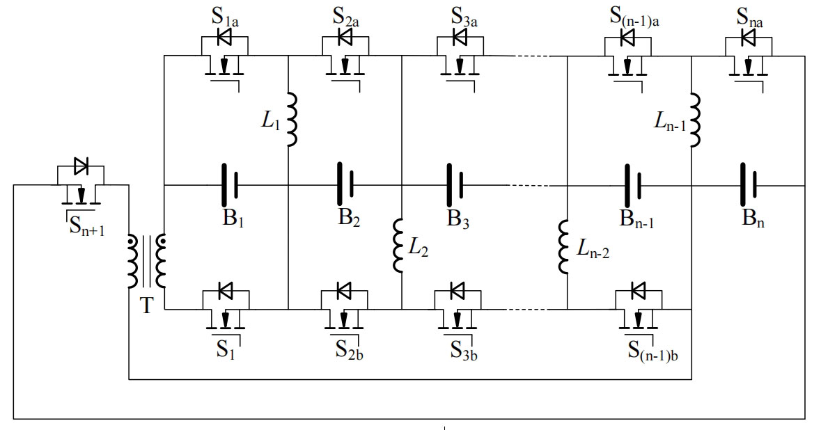
Figure 5 shows a hybrid single to single improved equalization circuit [33], which adds a one-to-one coupling transformer and two MOS transistors to the traditional inductive buck boost equalization circuit structure. The first and last two batteries of the battery pack can be directly balanced through transformers and MOSFETs S1 and Sn+1, optimizing the balancing problem of the longest path in traditional inductive buck boost balancing circuits. However, the problem of multi-step balancing for non longest balancing paths has not been solved, and it is also impossible to achieve direct balancing function for any individual or group of long chain battery packs, with few balancing paths and low balancing flexibility.
1.2 Direct Balanced Topology
Non direct balancing topology often requires multiple transformations in the balancing path of non adjacent battery cells in a long chain battery pack to achieve energy transfer. However, direct balancing topology circuits use their clever circuit structure to construct more direct balancing paths, significantly improving the drawbacks of low balancing efficiency and long balancing time caused by long balancing paths.
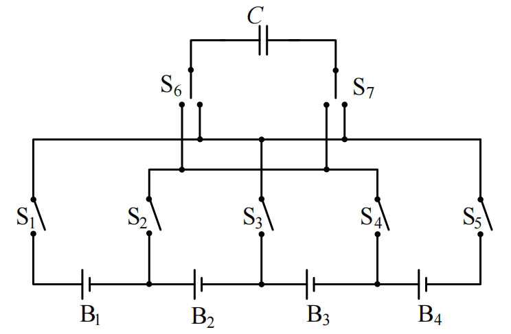
Figure 6 shows a single switched capacitor direct equalization circuit. This circuit only requires an intermediate energy storage capacitor. By controlling the bipolar switches at both ends of the capacitor and the switching tubes at both ends of the battery, a circuit is formed between the energy rich battery and the capacitor. After the capacitor stores energy, the switch direction is changed to form a circuit between the fully charged capacitor and the energy poor battery, thereby achieving energy transfer. This method can achieve direct balancing between any unbalanced units, and the circuit structure is also simple. However, the existing problems are also obvious. The switch capacitor balancing circuit needs to determine whether the voltage difference between battery cells is greater than a certain threshold in order to better transfer energy. The balancing effect is not thorough, and the capacitor has a large instantaneous peak current at the moment of switching, which is easy to cause damage to the battery.
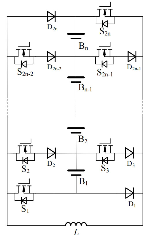
The direct balancing circuit of the flyover inductor is proposed by Korean scholars, as shown in Figure 7. This circuit only requires one flyover inductor to achieve multi-path energy transfer. Each battery cell is equipped with two sets of diodes and MOS transistors connected in series on one side. In addition to sharing a set of switching transistors on the battery sides at the beginning and end of the battery pack, both are used to control the energy transfer path, which can achieve any single cell to single cell, single cell to group The direct balancing between groups has a short balancing path and flexible unit expansion. However, for low voltage cells, the voltage drop loss of diodes is severe, and there is a problem with the freewheeling path during the blocking time of inductor switching switching switching.
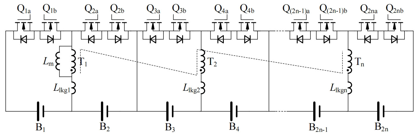
The fully coupled direct equalization circuit is shown in Figure 8. Each battery cell in the circuit has a set of bidirectional switches, and there is a coupling inductance between the cell numbers 2n-1 and 2n (n=1,2…), which can perform bidirectional Buck Boost mode equalization on two adjacent cells of the same winding. For non adjacent cells, flyback conversion mode can be used, but direct equalization between odd and even can only be performed according to the cell number, Otherwise, an additional step of direct equilibrium between adjacent monomers is required. Compared to the direct balancing circuit with flying inductors, the number of switching tubes is reduced, and the direct balancing path between individual cells is shorter, improving the balancing efficiency. However, it cannot achieve direct balancing between groups and lacks flexibility.