
In the rapidly evolving landscape of renewable energy, the role of battery energy storage systems has become increasingly critical for balancing supply and demand, enhancing grid stability, and ensuring the efficient utilization of intermittent power sources. Among the emerging technologies, sodium-ion batteries have garnered significant attention as a promising candidate for large-scale battery energy storage systems due to their cost-effectiveness, abundant raw materials, and enhanced safety profiles compared to their lithium-ion counterparts. However, the thermal behavior of these batteries, particularly the heat generated during charge and discharge cycles, poses a substantial challenge to their performance, longevity, and operational safety. The development of efficient thermal management strategies is therefore paramount for the widespread adoption of sodium-ion battery energy storage systems.
This study delves into the intricate heat-generation characteristics of sodium-ion batteries and proposes a novel, multi-stage variable flow rate thermal management strategy to optimize the performance of battery energy storage systems. Our approach combines experimental measurements with numerical simulations to unravel the non-symmetric heat generation profile between charging and discharging processes. The findings reveal that the heat generated during discharge is significantly higher—up to three times—than that during charging. This asymmetry, coupled with a stage-wise variation in heat generation power during discharge, forms the basis for our innovative cooling strategy. We demonstrate that by employing an asymmetric liquid cooling system with different flow rates for charging and discharging, and further refining the discharge process with a multi-stage variable flow rate approach, we can maintain optimal battery temperatures while substantially reducing the power consumption of the thermal management system. This work provides critical insights into designing more efficient and safer thermal management systems for large-scale sodium-ion battery energy storage systems.
The core of our investigation hinges on a comprehensive experimental analysis of a 210 Ah sodium-ion battery cell. Using an accelerating rate calorimeter, we meticulously measured the heat generation power and voltage profiles under 1P and 0.5P charge and discharge conditions, corresponding to power ratings of 555 W and 255 W, respectively. The results, summarized in the table below, highlight the starkly different thermal behaviors of the battery in its two operational modes.
| Operational Mode | Peak Heat Generation Power (W) | Total Heat Generated (Relative) | Key Stage-wise Behavior |
|---|---|---|---|
| 1P Discharge (555 W) | ~70 | High (3x charging) | Initial rise to 25 W, steady increase to 45 W, peak at 70 W, final surge and decay. |
| 1P Charge (555 W) | ~25 | Low | Sharp initial peak to 25 W, rapid decline to 12 W, brief rise to 15 W, then gradual decay. |
| 0.5P Discharge (255 W) | ~35 | Moderate | Gradual rise with two step-wise increases, followed by a sharp final decrease. |
| 0.5P Charge (255 W) | ~9 | Very Low | Initial peak of 9 W, rapid decline to near zero, with minimal subsequent activity. |
The data from Table 1 unequivocally demonstrates the non-symmetric nature of heat generation. Under the demanding 1P discharge condition, the peak heat generation power of 70 W is nearly three times the peak of 25 W observed during the 1P charge. Furthermore, the cumulative heat generated during discharge far exceeds that of charging. The 0.5P scenarios follow the same trend, with discharge producing significantly more thermal output. This asymmetry is the fundamental driver for our proposed thermal management optimization.
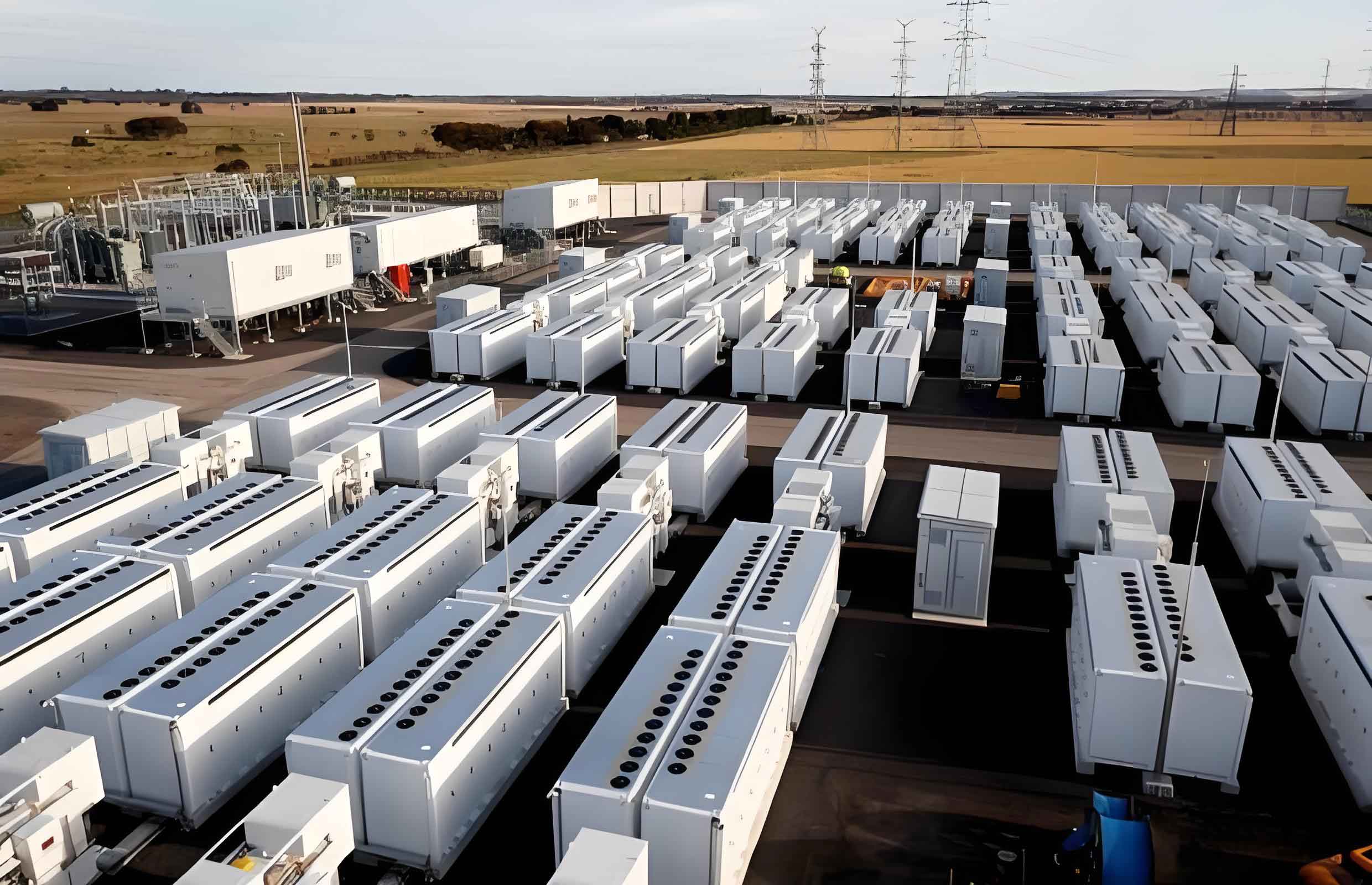
Based on these experimental findings, we constructed a detailed numerical model of a 1P52S battery module (52 cells in a 1-parallel-52-series configuration) integrated with a liquid cooling plate. The mathematical framework governing the system is built on fundamental conservation laws. For the fluid domain (coolant), the governing equations are the continuity, momentum, and energy equations, which can be expressed as:
$$ \frac{\partial \rho_f}{\partial t} + \nabla \cdot (\rho_f \mathbf{u}_f) = 0 $$
$$ \frac{\partial}{\partial t} (\rho_f \mathbf{u}_f) + \nabla \cdot (\rho_f \mathbf{u}_f \mathbf{u}_f) = -\nabla p_f + \nabla \cdot (\mu_f \nabla \mathbf{u}_f) $$
$$ \frac{\partial}{\partial t} (\rho_f c_{pf} T_f) + \nabla \cdot (\rho_f c_{pf} \mathbf{u}_f T_f) = \nabla \cdot (k_f \nabla T_f) $$
Where \(\rho_f\), \(\mathbf{u}_f\), \(p_f\), \(T_f\), and \(k_f\) represent the density, velocity vector, pressure, temperature, and thermal conductivity of the fluid, respectively. For the solid domains, including the battery cells themselves, the energy equation simplifies to:
$$ \frac{\partial}{\partial t} (\rho_b c_{pb} T_b) = \nabla \cdot (k_b \nabla T_b) + Q_{gen} $$
In this equation, \(\rho_b\), \(c_{pb}\), \(T_b\), and \(k_b\) are the density, specific heat capacity, temperature, and thermal conductivity of the battery, respectively. The critical term \(Q_{gen}\) represents the volumetric heat generation rate, which is directly sourced from our experimental ARC data, making our simulations highly realistic. The boundary conditions were set with a constant ambient temperature of 298 K and a combined convective and radiative heat transfer coefficient of 10 W/(m²·K).
The table below summarizes the thermophysical properties used for the key components of the thermal management system in the numerical model.
| Material | Density, \(\rho\) (kg/m³) | Thermal Conductivity, k (W/(m·K)) | Specific Heat Capacity, c\(_p\) (J/(kg·K)) |
|---|---|---|---|
| Coolant (Water) | 998.2 | 0.6 | 4182 |
| Liquid Cooling Plate (Aluminum) | 2719 | 202.4 | 871 |
| Battery Cell (Homogenized) | 2719 | \(\lambda_x=\lambda_y=20, \lambda_z=3\) | 871 |
Simulations of the 1P and 0.5P discharge scenarios validated our experimental observations. The maximum temperature of the module during a 1P discharge rose rapidly, reaching over 315 K, while during the 0.5P discharge, the temperature rise was more gradual, peaking around 309 K. For charging scenarios, the temperature increase was significantly less pronounced, with the 1P charge peaking near 302 K and the 0.5P charge barely rising above 299 K. This confirms that for battery energy storage systems, the cooling system must be primarily designed to handle the intense heat of the discharge cycle.
Our optimization strategy begins with an asymmetric approach, capitalizing on the inherent differences between charging and discharging. For the high-heat discharge process, we found that a mass flow rate of 0.4 kg/s for the coolant offered an optimal balance between temperature reduction and pumping power, reducing the maximum temperature by 1 K compared to 0.3 kg/s. For the low-heat charging process, our simulations showed that setting the mass flow rate to 0 kg/s (i.e., no active cooling) resulted in a maximum temperature of 304.4 K, which is still well within the safe operating range and significantly lower than the discharge temperatures. This single action yields a 100% reduction in thermal management power consumption during charging. The relationship between mass flow rate (\(\dot{m}\)) and the resulting maximum temperature (\(T_{max}\)) and pressure drop (\(\Delta P\)), a proxy for power consumption, during discharge is a key design function.
The most innovative aspect of our work is the multi-stage variable flow rate strategy for the discharge process. By analyzing the heat generation power profile during a 1P discharge, we identified three distinct stages: an initial low-power stage (0–2025 s), a mid-stage with peak heat generation (2025–2850 s), and a final decay stage (2850–4000 s). Instead of using a single, high flow rate for the entire discharge, we tailored the coolant flow to the instantaneous thermal demand of the battery energy storage system.
| Discharge Stage | Time Interval (s) | Heat Generation Power (Relative) | Proposed Mass Flow Rate (kg/s) |
|---|---|---|---|
| Initial Stage | 0 – 2025 | Low to Moderate | 0.2 |
| Peak Power Stage | 2025 – 2850 | High (Peak) | 0.3 |
| Final Decay Stage | 2850 – 4000 | Low, Decaying | 0.1 |
The performance of this multi-stage strategy was benchmarked against a constant high-flow rate scenario (0.6 kg/s). The comparison is critical for evaluating the efficiency gains. Our simulations revealed that the multi-stage variable flow rate strategy and the constant high-flow rate strategy achieved remarkably similar thermal control. The maximum temperature of the module was nearly identical in both cases (around 315.9 K for variable vs. 315.6 K for constant), and the minimum temperatures were also comparable (300.6 K vs. 299.7 K). This confirms that the adaptive strategy does not compromise thermal safety.
The primary advantage of the multi-stage variable flow rate strategy lies in its significant reduction in energy consumption. During the initial and final stages of discharge, where heat generation is low, the reduced flow rates lead to a substantially lower pressure drop across the cooling channels. The pressure drop (\(\Delta P\)) across the system is directly related to the pumping power (\(P_{pump}\)) required, as shown by the relationship:
$$ P_{pump} = \frac{\dot{m} \cdot \Delta P}{\rho \cdot \eta} $$
Where \(\eta\) is the pump efficiency. A lower pressure drop translates directly into lower power consumption for the thermal management system. In our simulations, the multi-stage strategy reduced the pressure drop by 64% in the initial stage and by a remarkable 91% in the final decay stage, compared to the constant high-flow rate of 0.6 kg/s. During the peak power stage, the flow was sufficient to prevent thermal runaway. The cumulative result is a battery energy storage system thermal management solution that is both highly effective and energy-efficient.
In conclusion, this research provides a comprehensive framework for optimizing thermal management in large-scale sodium-ion battery energy storage systems. We have experimentally confirmed the asymmetric and stage-wise heat generation characteristics of these batteries. Using this knowledge, we developed and validated a two-pronged optimization strategy. First, an asymmetric cooling approach uses different flow rates for charging and discharging, with charging requiring no active cooling. Second, a multi-stage variable flow rate strategy for the discharge process dynamically adjusts the coolant flow to match the battery’s instantaneous thermal load. This adaptive approach maintains the battery module’s maximum temperature within safe limits, matching the performance of constant high-flow cooling, while drastically reducing the energy required to run the cooling system, particularly during the low-heat phases of the discharge cycle. This work offers a practical and scalable pathway towards designing safer, longer-lasting, and more energy-efficient battery energy storage systems for grid-level applications.