
By studying the current development status of portable mobile power systems, this chapter will conduct a system requirements analysis based on specific characteristics such as portability and stability. Based on the system requirements, the overall architecture will be designed, and the architecture will be divided into modules for specific functional analysis.
1. Overall system design
1.1 System Requirements Analysis
Through the analysis of the overall performance of the portable mobile power supply system, it is concluded that the entire system has the following key design requirements:
(1) Portability: Mobile power supplies are commonly used for outdoor travel or work, so the system needs to meet multiple charging methods. When designing the charging module, the focus is on meeting a wide range of input voltages.
(2) Practicality: The system needs to provide multiple voltage output interfaces, which can output stable DC voltage to provide electricity for small devices such as mobile phones, tablets, USB fans, cigarette lighter devices, etc; It can also output AC power below 500W, providing electricity for mobile refrigerators, hair dryers, computers, and more.
(3) Real time performance: During the operation of the system, real-time system operation status information is displayed on the LCD screen, with a focus on battery level, output voltage, output power, interface status, and alarm information.
(4) Stability: This article is designed as a product that can be used for a long time, so the stability of the system is particularly important. During the design process, it is necessary to ensure the stability of the system during charging or discharging without damaging system components and load equipment.
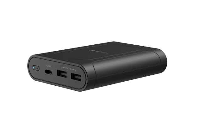
Based on the key requirements mentioned above, a portable mobile power supply system has been designed. The entire system can be equipped with various chargers, including adapters (12.6V/5A), photovoltaic panels (8-24V/100W), and car chargers (12V/10A). The external electrical energy can be transmitted to the lithium battery pack in the energy storage section for charging through the charging module. Design of discharge output module: AC discharge module and DC discharge module: The AC discharge module provides pure sine wave voltage (220V/50Hz) that is the same as the mains voltage, which is compatible with multiple devices and does not cause losses to them; The DC discharge module supplies DC power to various interfaces, such as the 12V/5A DC5521 interface, the 12V/10A cigarette lighter interface, and the USB interface for various fast charging protocols. At the same time, design control buttons to control the opening and closing of the system, and display the current operating status of the system through an LCD screen.
1.2 System Architecture Design
Based on the specific requirements mentioned above, analyze the overall architecture of the system. The entire system is mainly composed of charging module, discharging module, power management module, and other parts.
The function of the charging module is to adjust the DC voltage output by the charger and send it to the lithium battery pack for energy storage and charging. Due to the different chargers used in the system, the input voltage amplitude of the charging module varies. Therefore, a reasonable wide range voltage input control strategy should be designed in the control circuit of the charging module; The function of the discharge module is to convert the electrical energy stored in the lithium battery pack into DC or AC power required by different interfaces through the control circuit, and provide it to the load; The function of the power management module is to use the control chip to receive feedback signals from various modules of the system, and display the system’s operating status information on the LCD screen, making it convenient for users to monitor and protect the system in real time.
2. Architectural description of each module in the system
2.1 Architecture Description of Power Management Module
According to the requirements for power system control and monitoring, the power management module architecture is mainly composed of a control chip, display driver circuit, LCD display screen, and control buttons.
The entire system can control the output of AC voltage and DC voltage through peripheral buttons. During the operation of the system, the control chip collects the real-time operating status of the system, such as battery level, output power, output voltage, etc., and displays it in real time on the LCD screen through the driving circuit for users to obtain information. At the same time, if the system malfunctions, such as battery overvoltage, overcurrent, high temperature and other alarm signals, the control chip will immediately shut down the system operation process to protect the system from damage.
2.2 Description of charging module architecture
According to the charging requirements of the power system, the charging module architecture mainly consists of DC-DC converters, feedback systems, control systems, etc.
The logic controller in the charging module first collects input and output voltage signals, analyzes and processes them, and outputs reasonable control signals. It controls the driving system to drive the DC-DC converter for boosting or lowering operations, providing the output voltage to the lithium battery pack for energy storage and charging. Then, by receiving signals from the current and voltage feedback circuit, it changes the driving signal in real time to maintain system stability.
2.3 Description of discharge module architecture
The system discharge module is divided into AC output module and DC output module. The DC output module and charging module both use DC-DC converters for architecture design, similar to the design in the previous section, and will not be introduced here. According to the AC output requirements of the power system, the architecture of the AC discharge module is divided into two parts: the front-end boost part and the back-end inverter part.
The front-end boost section uses a DC-DC converter to boost the low DC voltage of the lithium battery pack. The front-end logic controller detects the battery voltage and feedback signal, and controls the DC-DC converter through the driving circuit to increase the battery voltage (12.6V) to DC high voltage (400V); The back stage inverter uses a DC-AC converter to convert the front stage DC high voltage into AC voltage for output. The back stage logic controller detects the voltage signal output by the front stage and the feedback signal from the back stage, and controls the DC-AC converter through the back stage drive circuit to invert the DC high voltage into a power frequency AC voltage (220V/50Hz) and output it to the load.
3. Summary
Based on the analysis of the requirements for portable mobile power systems, a complete system architecture diagram was designed, and then the entire system was modularized into power management module, charging module, and discharging module. The specific architecture and functional characteristics of each module were described.