
With the rapid advancement of coast guard operations, there is an increasing emphasis on integrating innovative technologies and renewable energy sources into maritime systems. For vessels engaged in long-range missions, the main engines cannot operate continuously around the clock. During scenarios such as anchoring or maintenance shutdowns of the primary power supply, a solar power system can efficiently supply electricity to the 24 V grid. In critical situations, this energy can be inverted to 220 V or 380 V for low-power daily appliances, ensuring uninterrupted operation of lighting, instrumentation, and living amenities. This approach not only conserves fuel resources but also significantly enhances the vessel’s endurance and self-sustainability, aligning with global trends in green energy adoption.
The fundamental principle of a solar power system revolves around the photovoltaic effect in semiconductors. This phenomenon directly converts light energy into electrical energy through the generation of electron-hole pairs at the semiconductor interface. When photons with sufficient energy strike a solar cell, they excite electrons from the covalent bonds in P-type and N-type silicon, creating electron-hole pairs. The junction between these semiconductors, known as the PN junction, establishes a potential difference. Upon illumination, holes in the P-type region migrate toward the N-type region, while electrons in the N-type region move toward the P-type region, resulting in an electric current from P-type to N-type. This process enables the semiconductor wafer to function as a reliable power source.
The current-voltage characteristics of a solar cell can be described by the diode equation, which is essential for understanding the efficiency of a solar power system. The general form is:
$$ I = I_L – I_0 \left( e^{\frac{qV}{nkT}} – 1 \right) $$
where \( I \) represents the output current, \( I_L \) is the light-generated current, \( I_0 \) is the reverse saturation current, \( q \) is the electron charge (approximately \( 1.602 \times 10^{-19} \, \text{C} \)), \( V \) is the voltage across the cell, \( n \) is the ideality factor (typically between 1 and 2), \( k \) is Boltzmann’s constant (\( 1.381 \times 10^{-23} \, \text{J/K} \)), and \( T \) is the absolute temperature in Kelvin. This equation helps in modeling the performance of solar panels under varying conditions, which is crucial for designing an effective solar power system for maritime use.
In practical applications, the efficiency \( \eta \) of a solar cell is given by:
$$ \eta = \frac{P_{\text{max}}}{P_{\text{in}}} \times 100\% $$
where \( P_{\text{max}} \) is the maximum power output and \( P_{\text{in}} \) is the incident solar power. For instance, with an average solar irradiance of 1000 W/m², a 300 W panel with 17.5% efficiency would require careful optimization to maximize energy harvest in marine environments.
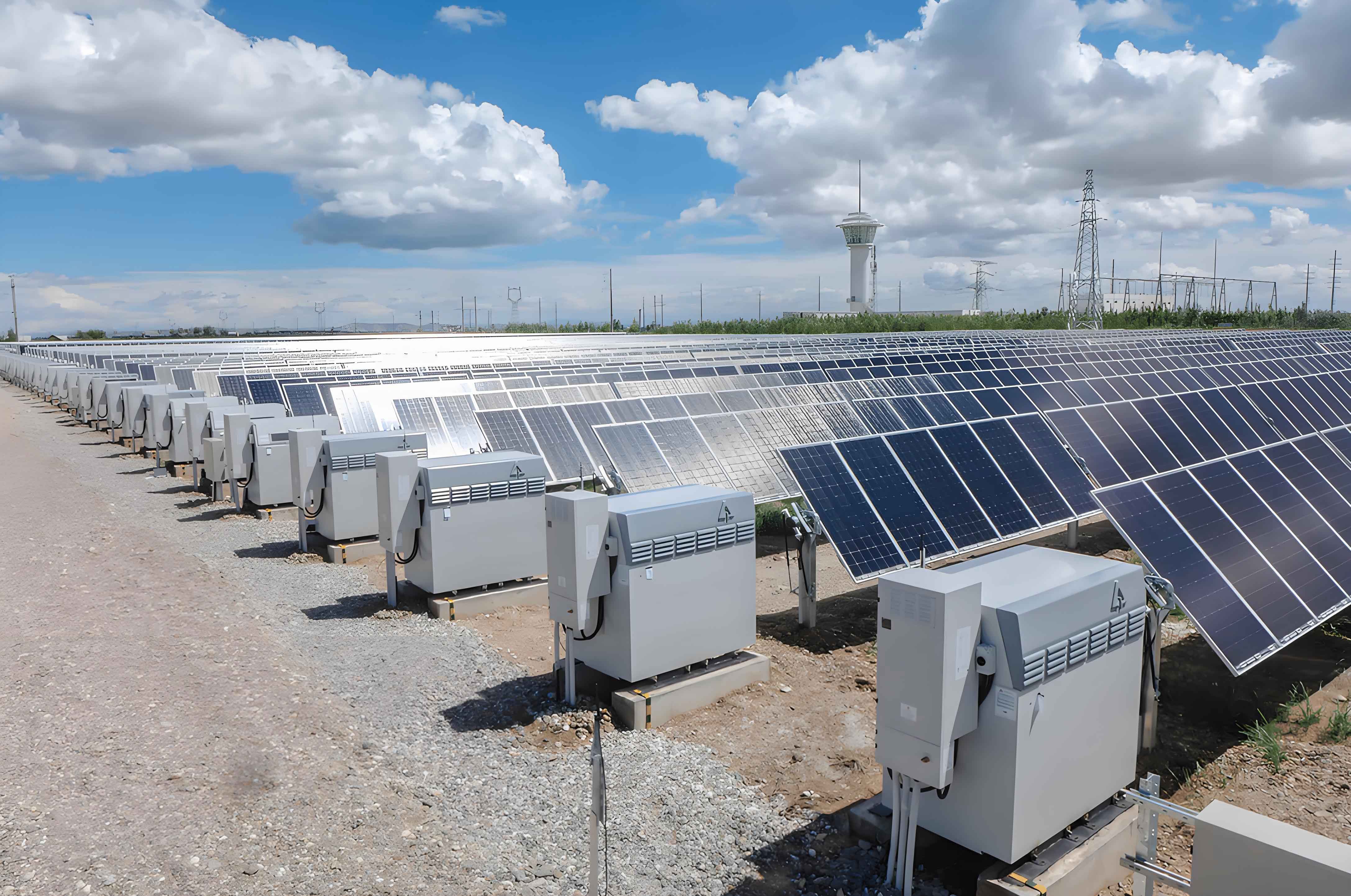
A typical solar power system comprises several key components: solar panels, charge controllers, inverters, battery banks, and a deployment control system. Each element plays a vital role in ensuring the reliability and efficiency of the system. The solar panels are the core, converting solar radiation into electrical energy, which is then stored in batteries. The charge controller regulates the charging process to prevent overcharging or deep discharge, thereby extending battery life. The inverter converts DC power to AC power for various applications, while the deployment system manages the extension and retraction of panels based on environmental conditions.
Here is a detailed summary of the components used in the proposed solar power system:
| Component | Specifications | Primary Function |
|---|---|---|
| Solar Panel | 300 W, 1960 mm × 990 mm × 45 mm, 25 kg, 17.5% efficiency | Converts sunlight into electrical energy |
| Charge Controller | 6-channel battery discharge detector with voltage range 10.2 V to 16.2 V | Monitors battery health and prevents overcharging/discharging |
| Inverter | 3200 W pure sine wave, output 220 V/50 Hz or 380 V | Converts DC to AC for appliances |
| Battery Bank | 12 V 200 Ah per battery, arranged in three sets of two | Stores energy for continuous supply |
| Deployment System | Servo motor with belt drive, controlled by photoresistor and relays | Automatically extends/retracts panels based on light and engine status |
The deployment control system utilizes a photoresistor to detect ambient light levels. When the main engine is off and sunlight is sufficient, the system activates a servo motor to extend the panels horizontally. Conversely, in low-light conditions or when the vessel is underway, the panels retract vertically to minimize wind resistance and damage. This automation is governed by a relay system linked to the engine’s operational status, ensuring that the solar power system only activates under safe conditions.
In the design for a specific coast guard vessel, we propose an automatic folding mechanism for the solar panels. The panels are deployed to replace the original sunshade on the aft deck, covering an area of approximately 18 m², and retracted against the superstructure wall when not in use. This design optimizes space utilization and maintains the vessel’s aerodynamic profile. The emergency grid is equipped with three sets of 24 V battery banks for low-voltage lighting, each consisting of two 12 V 200 Ah acid batteries, providing a robust energy reserve.
To determine the system parameters, we conducted calculations based on energy conservation principles. First, the energy stored in a single battery is calculated using the formula:
$$ W_{\text{battery}} = V \times \text{Ah} $$
For a 12 V 200 Ah battery:
$$ W_{\text{single}} = 12 \, \text{V} \times 200 \, \text{Ah} = 2400 \, \text{Wh} = 2.4 \, \text{kWh} $$
Since each bank comprises two batteries, the total energy per bank is:
$$ W_{\text{bank}} = 2 \times 2.4 \, \text{kWh} = 4.8 \, \text{kWh} $$
For three banks, the total energy storage capacity is:
$$ W_{\text{total}} = 3 \times 4.8 \, \text{kWh} = 14.4 \, \text{kWh} $$
Next, the peak sun hours at the installation site, such as the Ningbo maritime area, are determined. The annual solar radiation is approximately 7000 MJ/m². The peak sun hours can be estimated as:
$$ \text{Peak Sun Hours} = \text{Annual Radiation} \times 0.00076 $$
$$ \text{Peak Sun Hours} = 7000 \times 0.00076 = 5.32 \, \text{h} $$
This value is critical for sizing the solar power system accurately.
The discharge time for the battery banks under full load is calculated based on the load power. Assuming a load power of 4800 W (equivalent to the maximum output of the banks), the discharge time \( t \) is:
$$ t = \frac{W_{\text{total}}}{P} = \frac{14.4 \, \text{kWh}}{4.8 \, \text{kW}} = 3 \, \text{h} $$
This indicates that the batteries can sustain full load for 3 hours, which is sufficient for emergency scenarios.
To recharge the batteries fully in one day, the solar panels must supply 14.4 kWh. Using 300 W panels with an average daily energy output per panel calculated as:
$$ E_{\text{panel}} = \text{Power} \times \text{Peak Sun Hours} = 300 \, \text{W} \times 5.32 \, \text{h} = 1596 \, \text{Wh} \approx 1.6 \, \text{kWh} $$
The number of panels required is:
$$ N = \frac{W_{\text{total}}}{E_{\text{panel}}} = \frac{14.4}{1.6} = 9 $$
The total area occupied by the panels is approximately 18 m², as each panel covers about 2 m². This configuration ensures that the solar power system meets the daily energy demands efficiently.
For economic analysis, we compare the cost of the solar power system with conventional energy sources. The estimated cost breakdown is as follows:
| Item | Unit Price (USD) | Quantity | Total Cost (USD) |
|---|---|---|---|
| 300 W Solar Panel | 100 | 9 | 900 |
| Charge Controller | 80 | 1 | 80 |
| 3200 W Inverter | 220 | 1 | 220 |
| Deployment System | 140 | 1 | 140 |
| Installation and Miscellaneous | 200 | 1 | 200 |
| Total | 1540 |
If the same energy were generated by a diesel generator, the fuel consumption must be considered. Assuming a specific fuel consumption of 233 g/kWh, the daily fuel usage for 14.4 kWh is:
$$ \text{Daily Fuel} = 14.4 \, \text{kWh} \times 233 \, \text{g/kWh} = 3355.2 \, \text{g} = 3.355 \, \text{kg} $$
Annual fuel consumption is:
$$ \text{Annual Fuel} = 3.355 \, \text{kg/day} \times 365 \, \text{days} = 1224.6 \, \text{kg} \approx 1.225 \, \text{t} $$
At an estimated diesel cost of 1000 USD per ton, the annual fuel expense is approximately 1225 USD. Thus, the solar power system offers a payback period of about 1.5 years, highlighting its cost-effectiveness.
Alternatively, if shore power were used at a rate of 0.1 USD/kWh, the annual cost would be:
$$ \text{Annual Cost} = 14.4 \, \text{kWh/day} \times 365 \, \text{days} \times 0.1 \, \text{USD/kWh} = 525.6 \, \text{USD} $$
This further emphasizes the economic advantages of adopting a solar power system.
The feasibility of implementing a solar power system on coast guard vessels is supported by several factors. The available deck space (around 65 m²) comfortably accommodates the 18 m² panel array, allowing for potential expansion. When retracted, the panels fold compactly, minimizing wind resistance and preserving the vessel’s stability. The panels are protected by tempered glass, which offers resistance to salt corrosion, waves, and other marine hazards. The total system weight, under 1 ton, is negligible compared to the vessel’s displacement, ensuring no adverse effects on seakeeping or stability.
However, challenges include the intermittency of solar radiation, which necessitates reliable battery storage and may require backup charging during extended cloudy periods. The conversion efficiency of commercial solar panels typically ranges from 15% to 18%, limiting the power density that can be achieved. Inverters must be highly efficient and durable to handle the vessel’s electrical grid, and the marine environment demands robust materials to prevent degradation. Despite these issues, ongoing advancements in photovoltaic technology and energy storage are steadily addressing these limitations.
In summary, the integration of a solar power system into coast guard vessels presents a viable solution for enhancing operational autonomy and reducing environmental impact. While technical hurdles related to efficiency and durability persist, the benefits in terms of fuel savings, reduced emissions, and increased mission endurance are substantial. As research progresses, solar power systems are poised to become integral to maritime energy strategies, supporting sustainable and resilient coast guard operations worldwide. The continuous improvement in solar panel efficiency and battery technology will further solidify the role of renewable energy in naval applications.