
With the development of society and the improvement of people’s living standards, people’s demands for the safety of their living environment are increasing day by day. Safe and reliable alarm systems have begun to enter important units or public places such as shopping malls, shops, banks, and even some households have installed alarm systems. The performance of alarm systems is becoming increasingly important while ensuring the safety of public and personal property. At present, the functions of pyroelectric infrared alarm systems on the market are relatively single, which cannot provide better safety protection and cope with unexpected situations such as power outages. The solar infrared remote alarm system introduced in this article combines solar power with household power, alarm and video monitoring, and with ZigBee wireless hotspot transmission technology, it not only has stronger anti destructive ability than ordinary alarms, but also has the characteristics of environmental protection and low-carbon.
1. Overall design plan
1.1 Power supply module
(1) Solar power supplies power to various wireless devices and auxiliary power to wired devices.
(2) The solar household power supply is connected to a transformer device and a battery to form the power supply.
1.2 Infrared sensing module
The wireless pyroelectric infrared sensor utilizes a Fresnel lens to improve the sensitivity of the sensor and make the detection range of the sensor directional. It is connected to the infrared sensing signal processing circuit and then connected to the digital interface of the alarm control host. The wireless sensor is fixed in a concealed location and connected to the solar power battery. The signal is transmitted to the main control computer through the wireless communication chip. Multiple infrared sensing devices form an infrared sensing network, which comprehensively processes external signals through wireless sensing network programs.
1.3 GSM module
The module adopts a wireless dial-up transmission module, which is connected to the mobile phone dialer through RS232 serial port by the alarm control host, and dials the user’s mobile phone number according to the predetermined program.
1.4 Recording and alarm storage module
The embedded monitoring DVR module with large capacity hard disk storage for cameras can be configured with a large capacity hard disk as the front-end storage medium to achieve ultra long duration monitoring. Multiple cameras store images with good authenticity and retain all recorded information. To achieve weak current control and strong current, when the alarm control host sends a signal, the DVR module is controlled by a relay switch, and the camera automatically turns on or off recording. When the system is working, the alarm control host will issue a command to sound the alarm bell, and the LED indicator light will also turn red; When the system is in sleep, the alarm does not sound and the LED indicator light turns green.
2. Circuit Design
2.1 Main control circuit
The microcontroller adopts ATMEL’s AT89S52, which integrates 256B program running space and 8KBFLASH storage space internally. It supports external storage expansion of up to 64KB, and the clock frequency can be set between 0-33MHz. The on-chip resources include 4 sets of 32 I/O control ports, 3 16 bit timers, and 8 vector two-level interrupt structures The software is set in low energy mode, as well as watchdog and power-off protection. The main control circuit is shown in Figure 1.
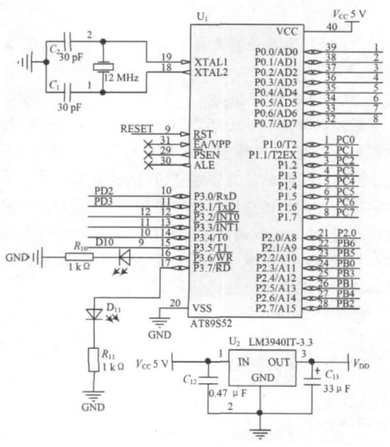
It operates normally within a wide voltage range of 4-5.5V, with low power consumption, and also supports computer parallel port downloading. AT89S52 has multiple packaging options, and DIP-40 packaging is used in this design.
2.2 Interface circuit between solar power generation and home power supply
The host adopts a dual power supply method of solar cells and household 220V power supply. When there is household electricity, cleverly disconnect the solar cell through a DC low-voltage relay; When the household electricity is disconnected, the solar cell acts as the power source. The solar cell is connected to the solar panel through a solar smart charger, which charges the battery when there is sufficient sunlight and automatically disconnects the charging when the battery is fully charged. In sufficient sunlight, the charging current can reach 1A or more, fully meeting the needs of the circuit.
2.3 GSM network access circuit
This system uses Siemens TC35 series GSM chip TC35i, which is compatible with GSM2/2, dual band (GSM900/GSM1800), and RS232 data interface. TC35i consists of six parts: power supply module (ASIC), flash memory, ZIF connector, antenna interface, etc. This module, along with the RF circuit and baseband, integrates to provide users with a standard AT command interface, providing fast, reliable, and secure transmission of data, voice, short messages, and faxes.
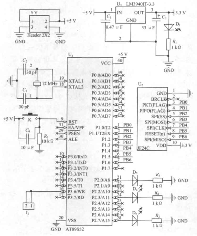
2.4 ZigBee protocol wireless communication circuit (slave)
The chip circuit is mainly based on the 2.4GHz bidirectional wireless transmission module JF24C. This module achieves data transmission with a small size, with a maximum speed of 1Mb/s, and features fast frequency hopping, forward error correction, CRC, and other functions. By transmitting signals from the controller, information is transmitted in the form of electromagnetic waves, and nearby chips control the corresponding JF24CJ to receive data, thereby achieving information transmission. The ZigBee circuit design module is shown in Figure 2.
2.5 Power circuit and alarm, video monitoring circuit
The solar power supply and video monitoring control circuit are shown in Figure 3.
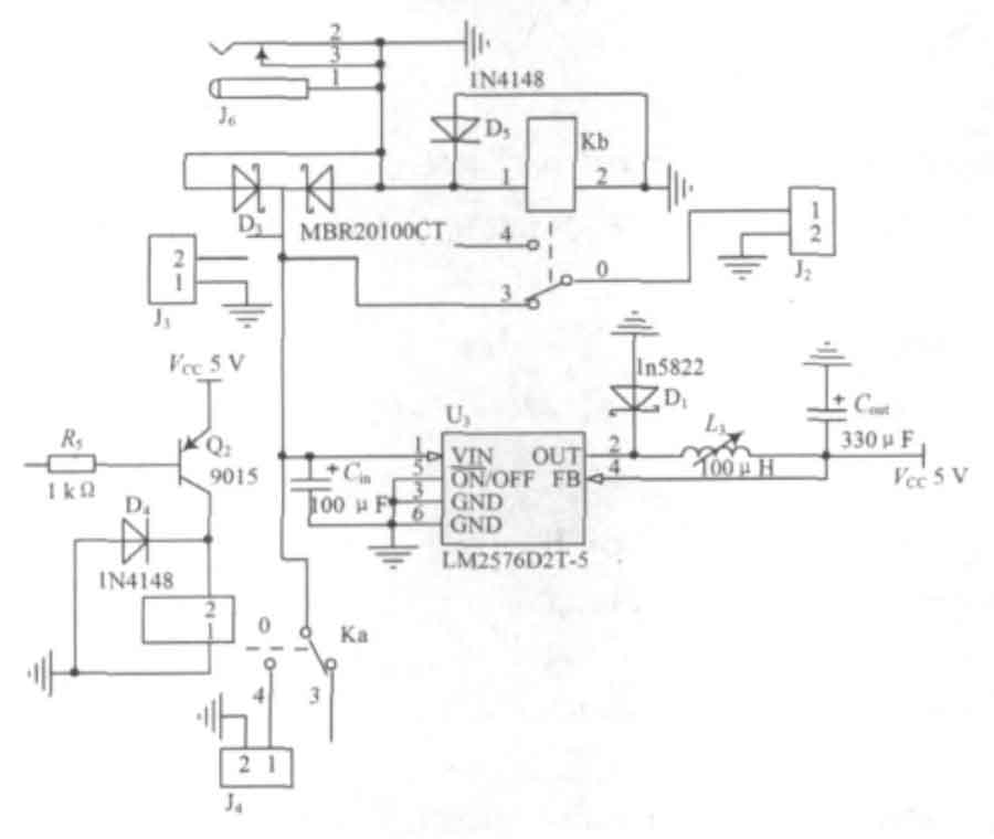
The alarm circuit adopts a simple and efficient transistor amplification circuit, which can be connected to a buzzer or a high-power alarm bell of 100dB or above can be selected. The video surveillance circuit adopts a DC relay with weak current control and strong current, with the coil terminal connected to a microcontroller and the DC current terminal connected to a DVR.
3. Experimental results
The working environment of the device was simulated indoors, and the solar panels were exposed to direct sunlight at a temperature of 24 ℃ for 14 hours. Three slave chips were coordinated to achieve signal detection and data transmission functions.
Connect the battery to the indoor power socket, turn on the main controller switch, and the LED interface will display English characters. After setting the alarm phone number, directly switch to the working mode. When approaching about 3.5m from slave 1, an alarm signal is sent from slave 1 and sent to the nearest slave 2. After detecting the alarm signal from slave 2, it is forwarded to the host. When the host receives an alarm signal, the display will display the word “TERMINAL1” and control the GSM module to make phone calls. At the same time, the alarm will sound, and the camera will perform the recording function and store the data. Connect the battery to the solar panel, disconnect the indoor power supply, and repeat the above actions to achieve the same function. After 30 experiments, the success rate of alarms was 28 times without any false alarms.
4. Conclusion
After on-site testing, the alarm success rate of the system is 93%, which can accurately achieve the alarm function.
This system is a successful trial application of ZigBee protocol and solar power generation in home anti-theft systems, and it is expected that the above two technologies will have broader prospects in the field of smart homes.