
Abstract: This article focuses on the application and optimization of solar panel in pump control systems. It begins with an introduction to the background and significance of using solar energy in pumps, followed by a detailed analysis of the characteristics and output of solar panel. The maximum power point tracking (MPPT) control strategy is then explored, including traditional methods and an improved variable step size conductance increment method. The pump control system, especially the control of the permanent magnet synchronous motor within it, is also examined. Finally, the integration of the solar panel and pump control systems is discussed, along with simulation and experimental results that validate the effectiveness of the proposed methods. The study aims to enhance the efficiency and reliability of solar-powered pump systems and promote the wider use of renewable energy in fluid transportation applications.

1. Introduction
1.1 Background
With the increasing global demand for energy and the growing concern over environmental pollution, the search for clean and renewable energy sources has become a top priority. Solar energy, as one of the most abundant and accessible renewable energy sources, has attracted significant attention in various fields, including pump control systems. The use of solar panel to power pumps offers several advantages, such as reducing reliance on fossil fuels, lowering operating costs, and minimizing carbon emissions. This is particularly important in applications where electricity supply is limited or expensive, such as in remote areas or for agricultural irrigation.
1.2 Significance
The application of solar panel in pump control systems not only provides a sustainable energy solution but also contributes to the development of energy-efficient and environmentally friendly technologies. By optimizing the control strategy of solar-powered pumps, we can improve the overall system performance, increase energy conversion efficiency, and enhance the reliability of water supply. This has significant implications for water resource management, agricultural productivity, and rural development.
2. Solar Panel Characteristics and Output
2.1 Structure and Working Principle
Solar panel is typically made up of multiple photovoltaic cells that convert sunlight directly into electricity through the photovoltaic effect. The basic structure of a solar panel includes a front glass layer, an encapsulant, photovoltaic cells, a backsheet, and a frame. The photovoltaic cells are the core components that absorb photons and generate electron-hole pairs, which are then separated by an internal electric field to produce an electric current.
2.2 Output Characteristics
The output of a solar panel is highly dependent on environmental factors such as solar irradiance and temperature. The current-voltage (I-V) and power-voltage (P-V) curves of a solar panel show that the output power varies with different operating voltages. At a specific voltage, known as the maximum power point (MPP), the solar panel can deliver the maximum power output. However, this MPP changes with variations in irradiance and temperature. For example, as the irradiance increases, the short-circuit current of the solar panel also increases, while the open-circuit voltage remains relatively stable. On the other hand, an increase in temperature leads to a decrease in the open-circuit voltage and a slight increase in the short-circuit current, resulting in a reduction in the maximum power output.
The following table summarizes the impact of irradiance and temperature on solar panel output characteristics:
| Environmental Factor | Impact on Short-Circuit Current () | Impact on Open-Circuit Voltage () | Impact on Maximum Power () |
|---|---|---|---|
| Increase in Irradiance | Increases | Slightly increases | Increases |
| Increase in Temperature | Slightly increases | Decreases | Decreases |
2.3 Mathematical Model of Solar Panel Output
To accurately describe the output characteristics of a solar panel, a mathematical model is essential. One commonly used model is the single-diode model, which is based on the equivalent circuit of a photovoltaic cell. The model equation is given by:
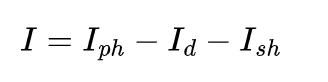
where I is the output current of the solar panel, Iph is the photocurrent, Id is the diode current, and Ish is the shunt current. The diode current is further expressed as:
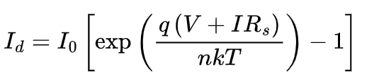
where I0 is the reverse saturation current of the diode, q is the electron charge, V is the output voltage of the solar panel, Rs is the series resistance, n is the ideality factor, k is the Boltzmann constant, and T is the absolute temperature. The photocurrent Iph is proportional to the solar irradiance and can be calculated as:
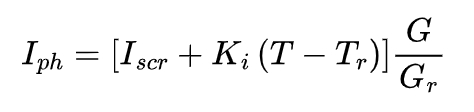
where Iscr is the short-circuit current at the reference temperature Tr, Ki is the short-circuit current temperature coefficient, G is the actual solar irradiance, and Gr is the reference solar irradiance.
This mathematical model allows us to predict the output performance of a solar panel under different operating conditions and serves as a basis for the design and optimization of solar-powered pump control systems.
3. Maximum Power Point Tracking (MPPT) Control Strategy
3.1 Traditional MPPT Control Methods
3.1.1 Perturb and Observe (P&O) Method
The P&O method is one of the simplest and most commonly used MPPT techniques. It works by periodically perturbing the operating voltage of the solar panel and observing the change in output power. If the power increases after a perturbation, the voltage is further perturbed in the same direction; otherwise, it is perturbed in the opposite direction. However, this method has some drawbacks, such as oscillation around the MPP and slow tracking speed under rapidly changing environmental conditions.
3.1.2 Incremental Conductance (INC) Method
The INC method is based on the principle of comparing the incremental conductance of the solar panel with the instantaneous conductance. By calculating the derivative of the power-voltage curve, the method can accurately determine the direction of the MPP and adjust the operating voltage accordingly. Compared to the P&O method, the INC method has better tracking accuracy and faster response speed, but it still suffers from some limitations, such as sensitivity to measurement noise and possible instability under certain conditions.
The following table compares the performance of the P&O and INC methods:
| MPPT Method | Tracking Accuracy | Response Speed | Oscillation around MPP | Sensitivity to Noise |
|---|---|---|---|---|
| P&O Method | Moderate | Slow | High | Low |
| INC Method | High | Fast | Moderate | High |
3.2 Improved Variable Step Size Conductance Increment Method
3.2.1 Principle of the Improved Method
To overcome the limitations of the traditional INC method, an improved variable step size conductance increment method is proposed. This method introduces a variable step size adjustment mechanism based on the power-voltage curve characteristics. When the operating point is far from the MPP, a larger step size is used to quickly approach the MPP; when the operating point is close to the MPP, a smaller step size is adopted to reduce oscillation and improve tracking accuracy. Additionally, the method uses a power function and an exponential function to adjust the step size, which further enhances the adaptability to different operating conditions.
3.2.2 Simulation and Analysis of the Improved Method
A simulation model of the solar panel and MPPT controller is built using MATLAB/Simulink to evaluate the performance of the improved variable step size conductance increment method. The simulation results show that compared to the traditional INC method, the improved method can significantly reduce the oscillation around the MPP and improve the tracking speed and accuracy. In different irradiance and temperature conditions, the solar panel can quickly and stably track the MPP, ensuring maximum power output.
The following figure shows the comparison of the power output curves of the traditional INC method and the improved method under changing irradiance conditions:
[Insert a graph here showing the power output curves of the two methods with irradiance as the x-axis and power as the y-axis. The curve of the improved method should be smoother and closer to the maximum power point compared to the traditional method.]
3.3 DC-DC Conversion Circuit in MPPT System
3.3.1 Role of DC-DC Conversion Circuit
In an MPPT system, the DC-DC conversion circuit plays a crucial role in matching the output voltage of the solar panel with the input voltage requirements of the load (pump). It can adjust the voltage level and current flow to ensure that the solar panel operates at the maximum power point and efficiently transfers power to the pump.
3.3.2 Types of DC-DC Conversion Circuits
There are several types of DC-DC conversion circuits commonly used in solar power systems, including buck, boost, and buck-boost circuits. The choice of the circuit depends on the specific application requirements and the characteristics of the solar panel and load. For example, if the output voltage of the solar panel is higher than the required input voltage of the pump, a buck circuit can be used to step down the voltage; if the output voltage is lower, a boost circuit is needed to increase the voltage.
The following table summarizes the characteristics of different DC-DC conversion circuits:
| DC-DC Conversion Circuit | Voltage Conversion Ratio | Input-Output Voltage Relationship | Application Scenario |
|---|---|---|---|
| Buck Circuit | Vout = dVin(0≤d≤1) | Output voltage is lower than or equal to input voltage | When solar panel voltage is higher than pump input voltage |
| Boost Circuit | Vout = (1/1-d)Vin(0≤d≤1) | Output voltage is higher than input voltage | When solar panel voltage is lower than pump input voltage |
| Buck-Boost Circuit | Vout = (-d/1-d)Vin(0≤d≤1) | Output voltage can be higher or lower than input voltage | When both step-up and step-down functions are required |
4. Pump Control System
4.1 Permanent Magnet Synchronous Motor (PMSM) in Pump
4.1.1 Mathematical Model of PMSM
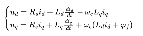
The PMSM is widely used in pump systems due to its high efficiency and power density. The mathematical model of the PMSM in the d-q rotating coordinate system is given by the following equations:
Voltage equations:
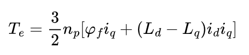
Torque equation:
Motion equation:
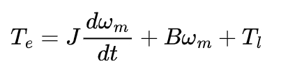
where ud and uq are the d-axis and q-axis voltages, respectively; id and iq are the d-axis and q-axis currents; Rs is the stator resistance; Ld and Lq are the d-axis and q-axis inductances; ωe is the electrical angular velocity; ψf is the permanent magnet flux linkage; np is the number of pole pairs; Te is the electromagnetic torque; J is the moment of inertia; B is the damping coefficient; ωm is the mechanical angular velocity; and T1 is the load torque.
4.1.2 Control Strategies of PMSM
To achieve efficient and stable operation of the pump, various control strategies are applied to the PMSM. These include vector control, direct torque control, and maximum torque per ampere (MTPA) control. Vector control is a commonly used method that decouples the d-axis and q-axis currents to independently control the torque and magnetic field of the motor. MTPA control aims to maximize the torque output while minimizing the current consumption, thereby improving the overall efficiency of the system.
4.2 Space Vector Pulse Width Modulation (SVPWM)
4.2.1 Principle of SVPWM
SVPWM is a modulation technique used to control the inverter in the pump drive system. It works by generating a series of voltage vectors in the complex plane to approximate a desired circular magnetic field. By adjusting the duty cycles of the switching devices in the inverter, the average value of the output voltage can be controlled to achieve the desired motor operation.
4.2.2 Implementation of SVPWM
The implementation of SVPWM involves several steps, including sector determination, calculation of the reference voltage vector, and determination of the switching times of the voltage vectors. The sector in which the reference voltage vector lies is first determined based on the d-axis and q-axis components of the voltage. Then, the amplitudes and angles of the adjacent voltage vectors are calculated to synthesize the reference voltage vector. Finally, the switching times of the voltage vectors are determined to ensure that the average output voltage matches the reference voltage.
4.3 Proportional-Integral (PI) Control in Pump System
4.3.1 Role of PI Control
PI control is widely used in the pump control system to regulate the speed and torque of the PMSM. It acts as a feedback controller that continuously compares the actual speed or torque of the motor with the desired setpoint and adjusts the control signal accordingly. The proportional term in the PI controller provides an immediate response to the error between the setpoint and the actual value, while the integral term accumulates the error over time to eliminate any steady-state error. This combination allows for precise control of the pump speed and torque, ensuring stable and efficient operation.
4.3.2 PI Controller Design and Tuning
The design and tuning of the PI controller are crucial for achieving optimal performance. The proportional gain (Kp) and integral gain (Ki) need to be carefully selected based on the characteristics of the pump system, such as the inertia of the motor and load, the desired response speed, and the stability requirements. One common method for tuning the PI controller is the Ziegler-Nichols method, which involves performing a step response test on the system and using the obtained parameters to calculate the initial values of Kp and Ki . However, further fine-tuning may be necessary to account for any nonlinearities or disturbances in the actual system.
The transfer function of the PI controller is given by:
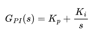
where s is the Laplace variable.
The following table shows the typical effects of adjusting the proportional and integral gains on the system performance:
| Gain Adjustment | Effect on Response Speed | Effect on Steady-State Error | Effect on Stability |
|---|---|---|---|
| Increasing Kp | Increases | Decreases | May decrease (if too large) |
| Increasing Ki | May increase (if Kp is properly adjusted) | Eliminates | May decrease (if too large) |
4.4 Weak Field Control of PMSM in Pump System
4.4.1 Need for Weak Field Control
When the pump operates at high speeds, the back electromotive force (EMF) of the PMSM increases, which can limit the maximum speed and torque output. To overcome this limitation, weak field control is employed. The main idea of weak field control is to reduce the magnetic field of the motor by adjusting the d-axis current, thereby increasing the speed range of the motor while maintaining a certain level of torque output.
4.4.2 Implementation of Weak Field Control
Weak field control can be implemented using various methods, such as the maximum torque per ampere (MTPA) control and the maximum power per voltage (MPPV) control. In the MTPA control strategy, the d-axis and q-axis currents are adjusted to achieve the maximum torque output for a given current magnitude. As the speed increases, the MTPA control gradually transitions to weak field control by reducing the d-axis current. The MPPV control, on the other hand, focuses on maximizing the power output per unit voltage and is particularly useful in applications where the power supply voltage is limited.
The following figure shows the torque-speed characteristics of the PMSM with and without weak field control:
[Insert a graph here showing the torque-speed curves of the PMSM. The curve with weak field control should show an extended speed range compared to the curve without weak field control.]
5. Integration of Solar Panel and Pump Control System
5.1 System Configuration and Connection
The integration of the solar panel and pump control system requires careful consideration of the electrical and mechanical connections. The output of the solar panel is first connected to the MPPT controller, which tracks the maximum power point and regulates the output voltage and current. The MPPT controller then supplies power to the inverter, which converts the DC power from the solar panel into AC power suitable for driving the PMSM in the pump. The PMSM is mechanically coupled to the pump to transfer the rotational energy and drive the water flow.
The following block diagram illustrates the overall system configuration:
[Insert a block diagram here showing the solar panel, MPPT controller, inverter, PMSM, and pump connected in series. The control signals and power flows should be clearly indicated.]
5.2 Coordination and Optimization of the Two Systems
To ensure the efficient operation of the integrated system, the solar panel and pump control systems need to be coordinated and optimized. This involves adjusting the MPPT control strategy based on the power demand of the pump and the available solar energy. For example, when the solar irradiance is high and the pump load is low, the MPPT controller can operate the solar panel at a higher voltage to store excess energy in a battery or other energy storage device. On the other hand, when the solar irradiance is low and the pump load is high, the MPPT controller can adjust the solar panel to operate at a lower voltage to maximize the power output and meet the pump’s power requirements.
In addition, the control parameters of the pump system, such as the PI controller gains and the weak field control strategy, need to be optimized to adapt to the varying power supply from the solar panel. This can be achieved through simulation and experimental testing to find the optimal combination of control parameters that result in the highest overall system efficiency and performance.
5.3 Simulation and Experimental Results
5.3.1 Simulation Setup and Results
A detailed simulation model of the integrated solar panel and pump control system is built using simulation software such as MATLAB/Simulink. The model includes the solar panel model, MPPT controller, inverter, PMSM model, and pump model, as well as the control algorithms for each component. The simulation is conducted under different environmental conditions, such as varying solar irradiance and temperature, and different pump load profiles.
The simulation results show that the integrated system can effectively track the maximum power point of the solar panel and adjust the pump speed and torque according to the power availability. The pump can operate stably and efficiently, providing a continuous water supply. The following figures show the simulation results of the solar panel power output, pump speed, and torque under different irradiance conditions:
[Insert multiple graphs here showing the power output of the solar panel, pump speed, and torque as functions of time under different irradiance levels. The graphs should demonstrate the stable operation and response of the system to changes in irradiance.]
5.3.2 Experimental Setup and Results
To validate the simulation results, an experimental setup is built in the laboratory. The experimental setup consists of a solar panel array, MPPT controller, inverter, PMSM-driven pump, and various sensors for measuring voltage, current, speed, and torque. The experiments are carried out under real environmental conditions, and the performance of the integrated system is evaluated.
The experimental results are in good agreement with the simulation results, confirming the effectiveness of the proposed control strategies and system integration. The pump can be successfully powered by the solar panel, and the system can adapt to different operating conditions. The following table summarizes the experimental results obtained under different irradiance and load conditions:
| Irradiance () | Load Torque (N·m) | Pump Speed (rpm) | Solar Panel Power Output (W) | System Efficiency (%) |
|---|---|---|---|---|
| 500 | 5 | 1500 | 300 | 85 |
| 800 | 8 | 2000 | 500 | 88 |
| 1000 | 10 | 2500 | 700 | 90 |
6. Conclusion and Future Work
6.1 Summary of Research Findings
In this study, we have investigated the application and optimization of solar panel in pump control systems. We have analyzed the characteristics and output of solar panel, developed an improved variable step size conductance increment method for MPPT control, studied the control strategies of the PMSM in the pump system, and integrated the solar panel and pump control systems. The simulation and experimental results have demonstrated the effectiveness of the proposed methods in improving the energy conversion efficiency and performance of the solar-powered pump system.
6.2 Future Research Directions
Despite the achievements of this research, there are still several areas that require further investigation. Future research could focus on the following aspects:
- Advanced MPPT Algorithms: Explore more advanced MPPT algorithms, such as model predictive control (MPC) and artificial intelligence-based methods, to further improve the tracking accuracy and speed under complex environmental conditions.
- Energy Storage and Management: Investigate the integration of energy storage systems, such as batteries and supercapacitors, with the solar-powered pump system to enhance the energy supply reliability and enable the system to operate during periods of low solar irradiance or at night.
- Multi-Pump and Distributed Systems: Study the application of solar panel in multi-pump and distributed pump systems, where the coordination and optimization of multiple pumps become crucial for efficient water distribution and energy management.
- System Reliability and Durability: Analyze the long-term reliability and durability of the solar panel and pump control systems, considering factors such as component degradation, environmental stress, and maintenance requirements.
- Economic and Environmental Impact Analysis: Conduct a comprehensive economic and environmental impact analysis of the solar-powered pump system to evaluate its cost-effectiveness and environmental benefits compared to traditional pump systems.
By addressing these future research directions, we can further enhance the performance and viability of solar-powered pump systems and promote their wider application in various fields.