
There are various loads carried by mobile power sources, among which there must be asynchronous motor loads. Asynchronous motors are an inductive load. When the mobile power source starts the asynchronous motor, the instantaneous current of the asynchronous motor suddenly increases significantly, and at the same time, it will cause a significant drop in the generation voltage of the mobile power source. If the generator design of the mobile power source is not reasonable, not only will it be unable to start the asynchronous motor, but it may even damage the precision instruments and equipment that have been loaded. Therefore, it is necessary to study the impact of asynchronous motor starting characteristics on mobile power generators, and seek suitable generator capacity design and generator technology for asynchronous motor starting.
1. Analysis of Starting Characteristics of Asynchronous Motors
1.1 Starting characteristics of asynchronous motors
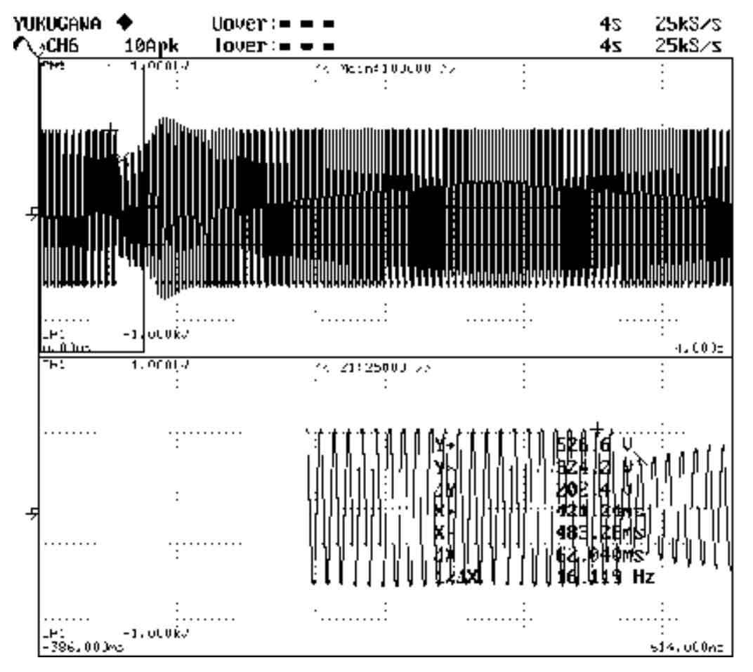
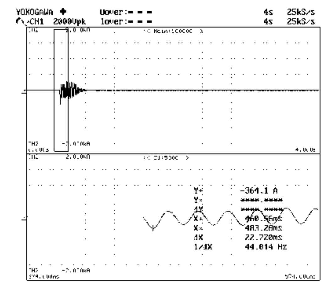
A 30kW generator powered by a mobile power source generates electricity and directly starts a no-load 22kW three-phase asynchronous motor. The voltage waveform (see Figure 1) and current waveform (see Figure 2) during the starting process of the motor are recorded. The peak voltage of the power line before starting is measured to be 526V, and the minimum peak voltage of the instantaneous line during starting is 324V. If the peak voltage drop of the instantaneous line is calculated to be 202V, the transient voltage drop is 202/526=38.4%. The maximum peak current of the starting moment is measured to be 364.1A, and the effective value of the maximum current is calculated to be 364.1/1.414=257.5A. However, if the effective value of the rated current of the 22kW three-phase asynchronous motor is 40A, the instantaneous starting current multiple is 6.4 times the rated current of the motor (257.5A). A/40A). The experiment shows that the instantaneous current when starting an asynchronous motor is extremely large, and the instantaneous voltage drop of the mobile power generator is deeper.
1.2 Maximum instantaneous current for different startup methods
The starting methods for asynchronous motors are direct starting and Y starting, respectively- Δ Start, voltage reduction start, and soft start, etc. Direct start: supply rated voltage power, motor winding Δ Start the motor when connected; Y- Δ Start: Supply the rated voltage power supply, connect the motor winding Y first to start, and then turn it on Δ Connect the starting motor; Voltage reduction start: supply power below rated voltage, motor winding Δ Start the motor when connected; Soft start: Use a soft start device to limit current and regulate voltage to start the motor.
The power supply start-up methods on the power side include single machine no-load start-up, dual machine no-load start-up, sequential start-up of multiple units, and unit load start-up. Single machine no-load start: Directly start the motor when a single generator set is unloaded; Dual machine no-load start: When two generator sets are connected in parallel with no load, the motor is directly started; Start multiple motors in sequence: Start multiple motors in sequence when the generator set is unloaded; Unit load start: The generator set starts the motor after carrying a certain load.
The different starting methods result in different current levels and voltage drops at the moment of starting. By comparing direct start, step-down start, and Y- Δ Analysis of start-up methods such as start-up and soft start shows that the maximum instantaneous current during direct start-up is 6.5 times the rated current of the asynchronous motor, Y- Δ Start is 6.5/3 times the rated current, and step-down start is 6.5 times the rated current × The multiple of starting voltage U/rated voltage UN, with the minimum instantaneous current during soft start. By analyzing the single machine and dual machine startup methods, adopting the dual machine startup method can increase the total power supply capacity, and the voltage drop during startup will be smaller, which is beneficial for the stable operation of electrical equipment.
2. Capacity analysis of mobile power generator design
2.1 Main performance requirements for mobile power supplies
A certain system requirement: The mobile power supply can directly start a 180kW three-phase asynchronous motor. The generator capacity design should meet the peak capacity requirements of the asynchronous motor during startup, and also assess the transient voltage and frequency indicators of the mobile power supply during startup:
1) Transient adjustment rate of generator voltage: ± 16%;
2) Engine frequency transient adjustment rate: ± 7%;
3) Transient adjustment rate of mobile power supply voltage: ± 23%.
2.2 Relationship between Generator Capacity and Voltage Drop at Start Moment
The assessment of the ability of a mobile power source to start an asynchronous motor depends on the degree of instantaneous voltage drop of the generator when starting the asynchronous motor, and is also affected by the instantaneous speed drop of the mobile power source engine. The formula for calculating the instantaneous voltage drop of the generator when starting an asynchronous motor is:
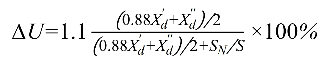
In the formula: ∆ U – Voltage drop/% when the generator suddenly applies load;
Xd ‘- per unit value of direct axis transient reactance of the generator;
Xd ” – per unit value of direct axis transient reactance of the generator;
SN – Rated capacity of generator/kVA;
S – Instantaneous capacity/kVA of suddenly added asynchronous motor.
The above equation indicates that when the capacity of the asynchronous motor to be started is determined, the instantaneous voltage drop of the generator when starting the asynchronous motor is not only related to the size of the generator capacity used, but also to the direct axis transient reactance and ultra transient reactance parameters of the generator.
2.3 Analysis of Generator Design Capacity
A single machine no-load starting motor with a water pump has a power of 180kW. When the single machine starts the motor, the instantaneous speed of the diesel engine drops by 7%. The generator capacity used is designed and analyzed according to the following two schemes, and the better one is selected.
Option 1: The rated power of the permanent magnet excitation generator is 760kW, with a capacity of SN=760/0.8=950kVA, Xd ‘=0.17, and Xd “=0.12.
Option 2: The rated power of the permanent magnet excitation generator is 880kW, with a capacity of SN=880/0.8=1100kVA, Xd ‘=0.09, Xd “=0.07.
For scheme one, calculate the instantaneous voltage drop of the generator when starting the asynchronous motor according to the following different starting methods. The calculation process is as follows, and the summary of the calculation results is shown in Table 1.
| Starting method | Generator transient reactance | Generator subtransient reactance | Generator capacity/kVA | Motor instantaneous capacity/kVA | Speed decrease by 0% | Speed drop of 7% |
| Code | Xd’ | Xd” | SN | S | ΔU | ΔU |
| Single machine direct start | 0.17 | 0.12 | 950 | 1462.5 | 18.90 | 25.90 |
| Dual machine direct start | 0.17 | 0.12 | 950 | 731.25 | 10.34 | 13.84 |
| Dual machine with 143kW load | 0.17 | 0.12 | 861 | 731.25 | 11.30 | 14.80 |
| Single machine Y – △ start | 0.17 | 0.12 | 950 | 487.5 | 7.12 | 14.12 |
| Start the first single machine first | 0.17 | 0.12 | 950 | 731.25 | 10.34 | 17.34 |
| Single machine restart for the second machine | 0.17 | 0.12 | 837.5 | 731.25 | 11.58 | 18.58 |
Single machine no-load direct start: When starting the motor, the instantaneous impulse current is 6.5 times the rated current, and the instantaneous capacity S=6.5 when starting the motor × 180/0.8=1462.5 (kVA), calculation: the instantaneous voltage drop during startup △ U=18.90%. Considering that the instantaneous speed drop during startup is 7% (when the single machine is in full load state), the total instantaneous voltage drop during startup △ U=25.90%.
Dual machine no-load direct start: The instantaneous capacity S=1462.5/2=731 (kVA) allocated to a single machine during startup is calculated as follows: the instantaneous voltage drop △ U=10.34% during startup. Considering that the instantaneous speed drop of the single machine during dual machine startup is 3.5% (when the single machine is in a half load state), the total instantaneous voltage drop △ U=13.84% during startup.
Starting with a load of 143kW for dual engines: The power of the single motor has decreased by 143/2=71.5 (kW) (capacity 89.4kVA), and the generator capacity SN=1950-89.4=861 (kVA). Calculation shows that the instantaneous voltage drop during startup is Δ U=11.30%. Considering that the instantaneous speed drop of the single machine during dual engine startup is 3.5% (when the single machine is at half load), the total instantaneous voltage drop during startup is Δ U=14.80%.
Single machine no-load Y- Δ Start: If the instantaneous impulse current during startup is 6.5/3 times the rated current, then the instantaneous capacity S=6.5 when starting the motor × 180/0.8/3=487.5 (kVA), calculation: the instantaneous voltage drop during startup △ U=7.12%. Considering the instantaneous speed drop during startup to 7% (when the single machine is in full load state), the total instantaneous voltage drop during startup △ U=14.12%.
The calculation for starting one 90kW motor before starting another 90kW motor with no load on a single machine:
At first startup: instantaneous capacity S=6.5 × 90/0.8=731.25 (kVA), calculation: the instantaneous voltage drop during startup △ U=10.34%, and the total instantaneous voltage drop △ U=17.34%.
At the second startup: the generator capacity decreased by 90/0.8=112.5 (kVA), the remaining capacity of the generator SN=950-112.5=837.5 (kVA), and the instantaneous starting capacity S=6.5 × 90/0.8=731.25 (kVA), calculation: the instantaneous voltage drop △ U=11.58% when the generator starts, and the total instantaneous voltage drop is △ U=18.58%.
According to the different starting methods mentioned above, calculate the instantaneous voltage drop of the generator when starting the asynchronous motor for Scheme 2. The calculation results are summarized in Table 2.
| Starting method | Generator transient reactance | Generator subtransient reactance | Generator capacity/kVA | Motor instantaneous capacity/kVA | Speed decrease by 0% | Speed drop of 7% |
| Code | Xd’ | Xd” | SN | S | ΔU | ΔU |
| Single machine direct start | 0.09 | 0.07 | 1100 | 1462.5 | 9.93 | 16.93 |
| Dual machine direct start | 0.09 | 0.17 | 1100 | 731.25 | 5.20 | 8.70 |
| Dual machine with 143kW load | 0.09 | 0.07 | 1011 | 731.25 | 5.63 | 9.13 |
| Single machine Y – △ start | 0.09 | 0.07 | 1100 | 487.5 | 3.52 | 10.52 |
| Start the first single machine first | 0.09 | 0.07 | 1100 | 731.25 | 5.20 | 12.20 |
| Single machine restart for the second machine | 0.09 | 0.07 | 987.5 | 731.25 | 5.76 | 12.76 |
Based on the above calculation and analysis, the calculated instantaneous voltage drop of a 760kW permanent magnet excitation generator directly starting a 180kW asynchronous motor without load is 25.90%, which exceeds the transient adjustment rate of ± 23% for the mobile power supply voltage. Therefore, the generator capacity design of Scheme 1 cannot be adopted; The instantaneous voltage drop calculation value of a 880kW permanent magnet excitation generator directly starting a 180kW asynchronous motor without load is 16.96%, which meets the requirement of a transient voltage adjustment rate of ± 23% for mobile power sources. Therefore, the generator capacity design in Scheme 2 should be adopted.
2.4 Comparison of Testing for Starting Asynchronous Motors
A 880kW permanent magnet excitation generator starts a 180kW asynchronous motor directly without load. The test value shows that the maximum peak current is 3142A, and the voltage drops from 397.9V to 328.9V. The voltage drop △ U=(397.9-328.9)/397.9=17.34%. The calculated and measured values of the instantaneous voltage drop are shown in Table 3.
A 880kW permanent magnet power excitation generator is used to start a 240kW asynchronous motor at no load. The test value shows that the maximum peak current is 5531A, and the voltage drops from 399V to 318.4V. The voltage drop △ U=(399-318.4)/399=20.19%. The calculated and measured values of the instantaneous voltage drop are shown in Table 3.
| Starting method | Generator transient reactance | Generator subtransient reactance | Generator capacity/kVA | Motor instantaneous capacity/kVA | Speed decrease by 0% | Speed drop of 7% | Instantaneous voltage drop measured value/% |
| Code | Xd’ | Xd” | SN | S | Δ U | Δ U | Δ U |
| Single machine direct start | 0.09 | 0.07 | 1100 | 1462.5 | 9.93 | 16.9 3 | 17.3 4 |
| Single machine direct start | 0.09 | 0.07 | 1100 | 1950 | 12.8 5 | 19.8 5 | 20.1 9 |
Comparative analysis between the calculated and measured values of instantaneous voltage drop in Table 3: The test values and calculated values of a 880kW permanent magnet excitation generator directly starting a 180kW asynchronous motor without load are basically consistent; The test values and calculated values of an 880kW permanent magnet excitation generator directly starting a 240kW asynchronous motor without load are basically consistent.
3. Generator technology suitable for asynchronous motor starting
Through the calculation and analysis of the voltage drop at the moment of starting the asynchronous motor mentioned above, the design capacity of the generator required for the mobile power source can be determined. At the same time, in order to minimize the voltage drop at the moment of starting the asynchronous motor, generator technologies that can adapt to asynchronous motor starting should also be adopted: ultra small transient reactance and ultra transient reactance technology, harmonic power excitation or permanent magnet power excitation technology, and high-level insulation technology.
3.1 Ultra small transient reactance and ultra transient reactance technology
In order to adapt to the starting of asynchronous motors, when designing the generator, it is advisable to use more iron cores and less copper, and to enhance damping design to reduce the direct axis transient reactance and super transient reactance values of the generator, so as to lower the transient voltage adjustment rate index of the generator and meet the requirements of sudden loading of high current load characteristics.
3.2 Harmonic power excitation or permanent magnet power excitation technology
The third harmonic power supply, as the excitation source of the generator, can vary with the size of the load current. When the load current is large, the harmonic excitation voltage will be high. The harmonic excitation voltage can increase in time with the increase of the starting current and has strong sustained ability, reducing the voltage drop at the moment of starting, which helps to start asynchronous motors.
Add a permanent magnet excitation generator, which generates a permanent magnet power supply as the excitation source for the generator. The permanent magnet power supply can provide a constant excitation power supply, which can provide a stable excitation power supply for the motor to start and stabilize the excitation energy of the generator when starting the motor.
3.3 High level insulation technology
The insulation level of the generator is selected as H-class insulation, and its temperature rise limit is limited according to the F-class insulation requirements. The stator and rotor windings of the generator are vacuum pressure impregnated with paint. The stator winding is made of enameled round copper wire with a temperature index of 200 degrees, and the rotor winding is made of glass wire wrapped flat copper wire with a temperature index of 200 degrees. The winding insulation reliability is high, making the generator have good voltage and temperature resistance performance.