
Under normal circumstances, solar cells can complete the conversion between light and electricity. It is composed of P-N junctions of semiconductors. Some materials can absorb electrons, such as boron, which forms some holes while absorbing electrons. Combining these materials with pure crystalline silicon forms P-type semiconductors. For N-type semiconductors, 5-valent chemical substances are mixed into pure silicon crystals to form holes with a few charge carriers. In terms of external electronegativity, both P-type and N-type are non electronegativity. The P-N junction refers to the joint region at the junction of P-type and N-type semiconductors, also known as the transition region.
Due to the imbalance between electron concentration and hole ratio at both ends of P-N, carrier dispersion occurs, and the movement of some carriers generates a potential difference, also known as contact potential difference. The magnitude can be expressed as follows:
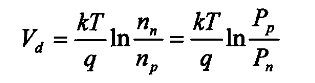
Among them: q is the electronic charge (1.6X10 ^ -16C);
T is the absolute temperature;
K is the Boltzmann constant;
Use Nn for N-type semiconductors and np for P-type semiconductor materials to represent electron concentration;
Use pn for N-type semiconductors and Pp for P-type semiconductor materials to represent hole concentration.
When sunlight shines on a solar cell, a portion of the sunlight will be reflected off, while another portion will be absorbed, and a small amount of sunlight will pass through the solar cell. This will generate photo generated electron hole pairs in the P and N regions of the solar cell. The photo generated electron hole pairs generated in the P region are separated and pushed towards the N region, while the hole pairs are left in the P region; The photo generated electron hole pairs generated in the N region drift under the action of the electric field force in the N region, leaving the photo generated electrons in the N region and the holes drift to the P region. Under this repeated action, the accumulation of positive and negative charges is formed, resulting in the generation of photogenerated electromotive force. It should be emphasized that the concentration of photogenerated electron hole pairs generated in the P and N regions is almost zero, which is the photovoltaic effect of solar cells.
(1) Solar cell power testing conditions
Solar cells are subject to certain environmental influences during operation, including factors such as light source illumination, battery temperature, and lighting. Therefore, when testing the power of solar cells, environmental factors need to be taken into account. Currently, there is an international standard for monitoring solar cells;
The irradiance of the light source is 1000W/m ^ 2;
The test temperature is: 25 ° C;
The illumination amplitude is obtained based on the analysis of AM1.5 ground spectral illuminance. Please refer to the literature for spectral illuminance.
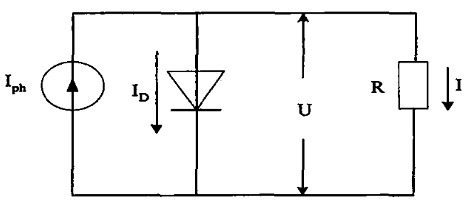
(2) The working principle of solar cells
The main reason for the generation of current Iph in solar power generation is that sunlight is mapped onto the solar panel, and its equivalent circuit is a constant current source, which we call photocurrent. The diode in parallel with it is in a positive bias state, and its leakage current ID is called dark current. The two have opposite directions, so dark current has a certain counteracting effect on photogenerated current. The dark current ID can be represented as follows:
In the formula: I0 is the reverse saturation current;
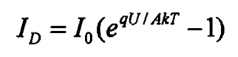
U is the equivalent diode terminal voltage;
Q is the electronic quantity of electricity;
T is the absolute temperature;
A is the diode curve factor;
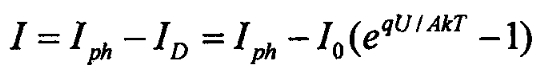
Therefore, the working current at both ends of the load:
(3) The equivalent circuit of actual solar cells
Usually, in practice, solar cells themselves also have series and parallel resistors, and the reason for the phenomenon of seed delivery is due to the formation of dirt and defects on the semiconductor itself and the surface of the solar cell. Usually, these resistance values are several thousand ohms. Therefore, the actual equivalent circuit of a solar cell is shown in Figure 2.
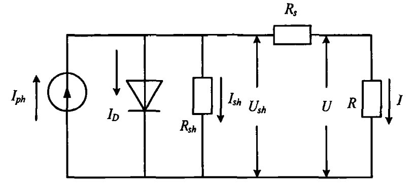
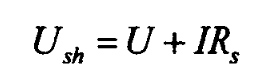
The voltage at both ends of Rsh in the figure is:
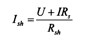
The current flowing through it is:
The current flowing through load R is:
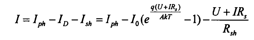
In the above equation, Iph is the photogenerated current and I0 is the dark current, which are determined by environmental conditions and some specific physical properties of solar cells. Their expressions can be written as:
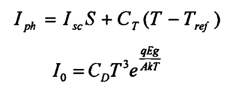
In the above equation, A is the PN junction coefficient of the photovoltaic semiconductor, k is the Boltzmann constant, Isc is the short-circuit current, is the reference temperature, S is the illumination intensity, Eg is the semiconductor bandgap energy, CT is the compensation coefficient for photogenerated current, and CD is the compensation coefficient for dark current.
It can be seen from the current flowing through load R that reducing Rs and increasing Rsh can make the solar cell closer to idealization.