
Addressing the significant energy consumption of infrastructure, particularly in transportation, is a critical component of global efforts to achieve carbon neutrality. The operational phase of roads presents a substantial challenge, with tunnel lighting systems being a predominant energy consumer. This study explores the integration of thin film solar panel technology into the architectural design of tunnel portals as a viable and sustainable solution. By transforming tunnel sunshades into power-generating entities, this approach directly offsets the conventional grid electricity required for illumination, promoting energy self-sufficiency and reducing the carbon footprint of vital urban river crossings. This analysis provides a comprehensive methodological framework and quantitative assessment of the energy and emission benefits, using a specific large-diameter shield tunnel as a case study to demonstrate the scalability and effectiveness of this green technology.
The imperative for deep decarbonization across all economic sectors has never been clearer. Within the construction and operation of transportation infrastructure, achieving meaningful reductions in greenhouse gas emissions requires innovative approaches that go beyond incremental efficiency gains. Tunnels, especially long urban under-river passages, are essential for modern connectivity but are energy-intensive assets during their operational lifespan. Research indicates that lighting can account for over half of a tunnel’s total operational energy use, presenting a clear target for intervention. Solar energy, as an abundant, clean, and renewable resource, offers a compelling alternative. The advent of flexible, semi-transparent thin film solar panels creates new opportunities for building-integrated photovoltaics (BIPV). These panels can be seamlessly incorporated into structures like tunnel portal sunshades, which are traditionally non-energy-generating architectural elements. This integration not only preserves the sunshade’s primary function of mitigating the “black hole” effect for drivers but also turns it into a local, clean power plant. Despite the evident potential, a detailed, project-specific quantification of the carbon reduction and economic benefits from such integrations is often lacking, which can hinder broader adoption by project planners and developers. This work aims to bridge that gap by presenting a detailed calculative model and a definitive case study to underscore the tangible advantages of retrofitting or designing tunnel sunshades with thin film solar panel technology.
Case Study: The Shunde Waterway Crossing Tunnel
This analysis is based on the Shunde Waterway Crossing, a critical segment of the Jihua Road West Extension project in Foshan City, China. As a large-scale urban infrastructure project, it represents a typical scenario where energy-saving measures can have a substantial impact. The tunnel is a twin-tube, bidirectional six-lane shield tunnel with a total length of 2,655 meters. The shield-driven section itself is 1,472 meters long, with an external diameter of 15 meters and an internal clearance height of 7.8 meters. The design speed for the mainline is 80 km/h. This project serves as an excellent model for assessing the application of thin film solar panel systems due to its scale and urban context.
Analysis of Tunnel Lighting Energy Demand
The accurate determination of lighting demand is the foundational step for sizing any complementary power generation system. Tunnel lighting is meticulously segmented to ensure driver safety by gradually adapting the human eye to drastic changes in luminance when entering and exiting.
Calculation of Lighting Zone Lengths
Following established design guidelines, the lighting zones and their respective lengths are calculated based on the tunnel’s geometric and operational parameters: design speed (v = 80 km/h), internal height (h = 7.8 m), and total length (D = 2655 m). The stopping sight distance (Ds) is a key parameter, taken as 100m for the design speed. The calculations for each zone are summarized below:
| Lighting Zone | Segment | Calculation Method | Length (m) |
|---|---|---|---|
| Entrance Zone | Entrance 1 (Din1) | $$D_{in1} = \frac{1}{2} \left( \frac{1.154D_s – h – 1.5}{\tan(10^\circ)} \right)$$ | 39.8 |
| Entrance 2 (Din2) | $$D_{in2} = D_{in1}$$ | 39.8 | |
| Intermediate Zone | Intermediate (Dth) | $$D_{th} = D – D_{in} – D_{tr} – D_{ex}$$ | 2222.1 |
| Transition Zone | Transition 1 (Dtr1) | $$D_{tr1} = \frac{D_{in1}+D_{in2}}{3} + \frac{v}{1.8}$$ | 71.0 |
| Transition 2 (Dtr2) | $$D_{tr2} = \frac{2v}{1.8}$$ | 88.9 | |
| Transition 3 (Dtr3) | $$D_{tr3} = \frac{3v}{1.8}$$ | 133.3 | |
| Exit Zone | Exit 1 (Dex1) | Empirical Value | 30.0 |
| Exit 2 (Dex2) | Empirical Value | 30.0 |
Determination of Required Luminance Levels
The required luminance (L) for each segment depends on the external luminance (L20), taken as 4000 cd/m² for this scenario, and the design speed. The calculations use a threshold increment (k) of 0.035.
| Lighting Zone | Segment | Calculation Method | Luminance (cd/m²) |
|---|---|---|---|
| Exterior | Exterior (L20) | Reference Value | 4000 |
| Entrance Zone | Entrance 1 (Lin1) | $$L_{in1} = k \cdot L_{20}$$ | 140 |
| Entrance 2 (Lin2) | $$L_{in2} = 0.5 \cdot k \cdot L_{20}$$ | 70 | |
| Intermediate Zone | Intermediate (Lth) | Reference Value | 3.5 |
| Transition Zone | Transition 1 (Ltr1) | $$L_{tr1} = 0.15 \cdot L_{in1}$$ | 21 |
| Transition 2 (Ltr2) | $$L_{tr2} = 0.05 \cdot L_{in1}$$ | 7 | |
| Transition 3 (Ltr3) | $$L_{tr3} = 0.02 \cdot L_{in1}$$ | 2.8 | |
| Exit Zone | Exit 1 (Lex1) | $$L_{ex1} = 3 \cdot L_{th}$$ | 10.5 |
| Exit 2 (Lex2) | $$L_{ex2} = 5 \cdot L_{th}$$ | 17.5 |
Total Luminous Flux and Annual Energy Consumption
The total luminous flux demand (Φ) dictates the number and power of luminaires required. It is calculated by summing the product of required illuminance (E) and area for each segment. Illuminance is derived from luminance and the road surface reflection coefficient (R = 0.13 for standard asphalt). For a road width (S) of 10.8 meters, the total flux is calculated as:
$$ \Phi = \sum_{i=1}^{n} E_i \cdot D_i \cdot S = \sum_{i=1}^{n} \frac{L_i}{R} \cdot D_i \cdot S $$
This yields a total luminous flux demand of approximately 1.6174 million lumens. Using this value, the minimum number of LED luminaires of different wattages (150W, 80W, 40W) can be determined. The total installed power (Wlight) and subsequent annual energy consumption (Eannual), assuming 24/7 operation, are calculated. The results for different lighting schemes are shown below.
| Scheme | Luminaire Power (W) | Lumens per Fixture | Min. Number of Fixtures | Total Installed Power (kW) | Annual Energy Consumption (MWh) |
|---|---|---|---|---|---|
| 1 | 150 | 18000 | 90 | 13.5 | 118.3 |
| 2 | 80 | 9000 | 180 | 14.4 | 126.1 |
| 3 | 40 | 4400 | 368 | 14.72 | 128.9 |
Therefore, the tunnel’s lighting system has an annual energy demand ranging from 118.3 to 128.9 MWh.
Power Generation Capacity of the Thin Film Solar Panel System
The core of this solution lies in the thin film solar panel array integrated into the tunnel portal sunshade. The power generation capacity is a function of the system’s total installed capacity, which itself depends on the area covered and the specific performance of the thin film solar panels used.
Design of the Photovoltaic Sunshade
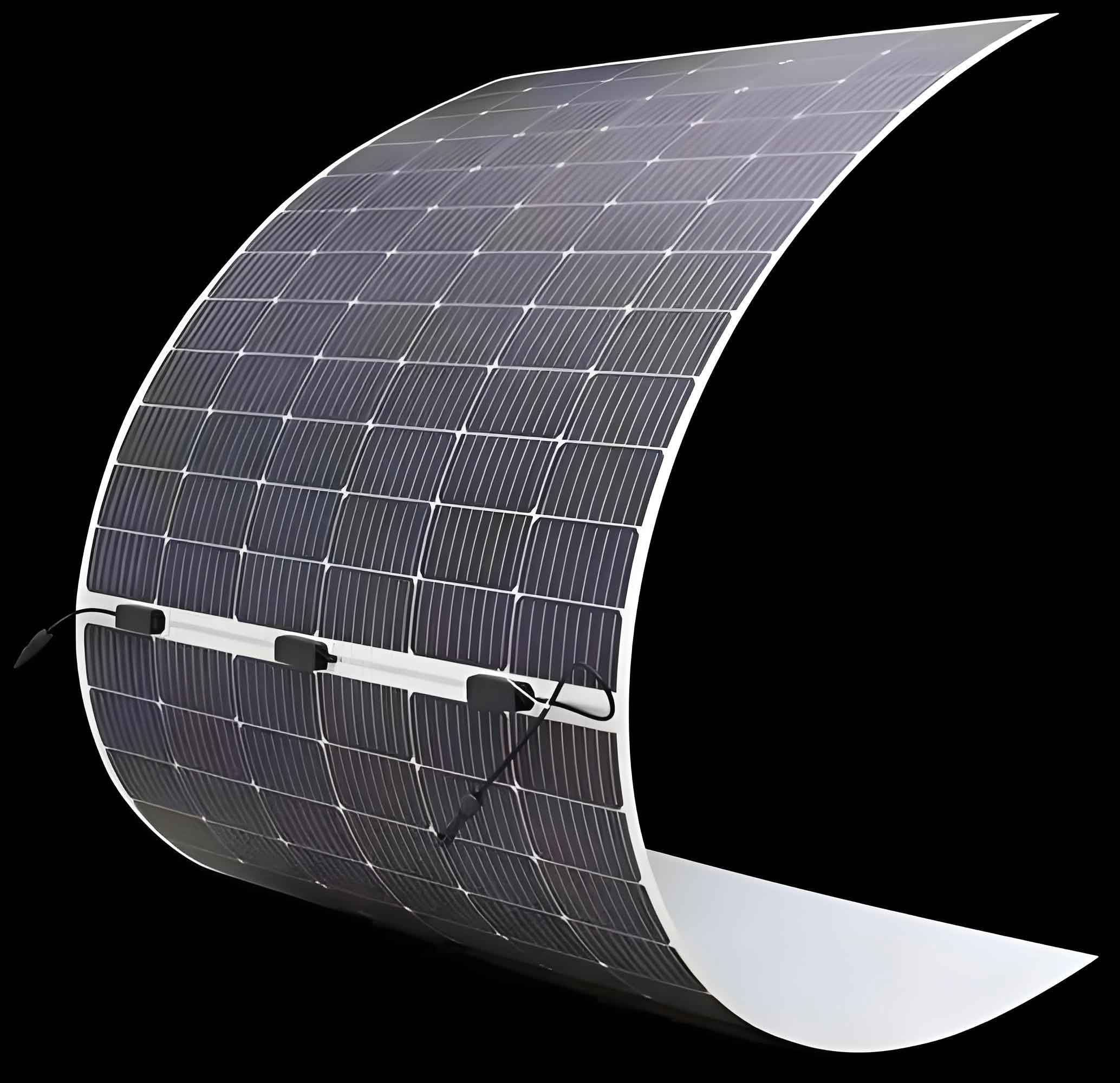
The proposed sunshade for the Shunde Waterway Tunnel is designed with a length (Ltotal) of 80 meters and an extended width (B) of 32 meters, providing a significant surface area for thin film solar panel installation. To manage the gradient of light transmission from the bright exterior to the darker tunnel interior, a combination of thin film solar panels with different transmittance levels is proposed. Typically, panels with 40% and 15% light transmittance are used. The lower the transmittance, the higher the power conversion efficiency and power density. The power generation capacity (WPV) of the sunshade is given by:
$$ W_{PV} = \frac{1}{1000} \sum_{j} ( \eta_j \cdot w_{0,j} \cdot S_{g,j} ) $$
$$ S_{g,j} = L_{g,j} \cdot B $$
Where:
ηj is the utilization coefficient for thin film solar panels of transmittance ‘j’ (0.592 for 40%, 0.892 for 15%),
w0,j is the nominal power per square meter (57.852 W/m² for 40%, 87.185 W/m² for 15%),
Sg,j is the applied area for panel type ‘j’,
Lg,j is the applied length along the sunshade for panel type ‘j’.
Scenario Analysis and Annual Energy Yield
Five different design scenarios are analyzed by varying the proportion of the sunshade covered by each type of thin film solar panel. The total installed capacity and the estimated annual energy yield are calculated for each scenario, considering the local average annual sunshine hours (1,629 hours) and an estimated system efficiency yielding equivalent utilization hours between 765 and 840 hours per year.
| Scenario | Length with 40% Panels, L40 (m) | Length with 15% Panels, L15 (m) | Total Installed Capacity, WPV (kW) | Estimated Annual Energy Yield (MWh) |
|---|---|---|---|---|
| 1 | 0 | 80 | 199.09 | 162.7 |
| 2 | 20 | 60 | 171.24 | 140.0 |
| 3 | 40 | 40 | 143.38 | 117.2 |
| 4 | 60 | 20 | 115.53 | 94.4 |
| 5 | 80 | 0 | 87.68 | 71.7 |
The analysis reveals that Scenarios 1 and 2, where thin film solar panels with 15% transmittance cover at least 75% of the sunshade length, generate more than enough electricity to fully cover the tunnel’s annual lighting demand (118.3-128.9 MWh). Even Scenario 3 comes very close to achieving self-sufficiency for lighting. This clearly demonstrates the technical viability of using a thin film solar panel system on tunnel sunshades to meet a major operational energy load.
Assessment of Energy Saving, Carbon Reduction, and Economic Benefits
The integration of thin film solar panels translates direct solar energy into quantifiable operational benefits. The assessment is presented from two perspectives: 1) Benefits from fully offsetting the tunnel lighting load, and 2) Total benefits from all electricity generated by the thin film solar panel array.
Energy Saving (Standard Coal Equivalent)
Using the national average grid electricity coal consumption rate of 302.5 grams of standard coal per kWh (2021 data), the energy saving is calculated as:
$$ \text{Coal Saved} = E_{\text{saved}} \times 0.3025 \, \text{kg/kWh} $$
- Lighting Load Offset: Saving 118.3 – 128.9 MWh avoids the consumption of 35.77 – 39.01 tonnes of standard coal annually.
- Total PV Generation: The entire system output of 71.7 – 162.7 MWh equates to saving 21.68 – 49.22 tonnes of standard coal annually from the regional grid.
Carbon Dioxide Emission Reduction
Using the 2022 national grid emission factor of 0.581 tonnes of CO₂ per MWh, the carbon reduction is:
$$ \text{CO}_2 \text{ Reduced} = E_{\text{saved}} \times 0.581 \, \text{t/MWh} $$
- Lighting Load Offset: Reduces carbon emissions by 68.71 – 74.92 tonnes of CO₂ annually.
- Total PV Generation: Reduces carbon emissions by 41.65 – 94.54 tonnes of CO₂ annually.
Economic Benefit (Operational Cost Saving)
Based on the local commercial electricity tariff of 0.7264 CNY/kWh, the direct financial saving on electricity bills is:
$$ \text{Cost Saved} = E_{\text{saved}} \times 0.7264 \, \text{CNY/kWh} $$
- Lighting Load Offset: Saves 85,900 – 93,700 CNY in annual operational costs.
- Total PV Generation: Provides 52,100 – 118,200 CNY in annual economic value.
Feasibility Analysis and Implementation Considerations
The quantitative results strongly support the feasibility of thin film solar panel integration for urban tunnel sunshades. The key advantage of thin film technology in this context is its flexibility and suitability for integration into curved or non-standard architectural forms, unlike rigid crystalline silicon panels. The ability to select different transmittance levels allows designers to balance energy generation with the necessary psychological and safety lighting transition for drivers. For a new tunnel project, the thin film solar panel system can be designed in from the outset, optimizing the structural and electrical integration. For retrofitting existing tunnels, a structural assessment of the sunshade is required, but the lightweight nature of thin film solar panels is a significant advantage. The primary economic consideration is the initial capital investment for the thin film solar panels, power conditioning units, and potential storage or grid-connection equipment. However, as demonstrated, the annual savings on electricity bills and the associated reduction in carbon liabilities create a compelling payback proposition. Furthermore, this application aligns perfectly with green building certifications and sustainable infrastructure policies, potentially unlocking additional funding or regulatory advantages.
Conclusion
This detailed analysis confirms that the integration of thin film solar panel technology into the sunshades of urban large river crossing tunnels presents a highly effective and scalable strategy for operational decarbonization. Using the Shunde Waterway Tunnel as a representative case, the study establishes a clear methodological framework for calculating lighting demand, sizing a thin film photovoltaic system, and quantifying the subsequent benefits. The results show that a properly sized thin film solar panel array on the portal sunshade can not only meet but potentially exceed the annual electricity consumption of the tunnel’s lighting system. This translates into substantial annual savings of 35-39 tonnes of standard coal, reductions of 69-75 tonnes of CO₂ emissions, and operational cost savings of 85,000-93,000 CNY for the lighting load alone. The flexibility, architectural integration potential, and strong energy yield of modern thin film solar panels make them an ideal technology for this application. Therefore, incorporating thin film solar panels into the design of new tunnel sunshades or planning their retrofitting on existing structures should be considered a best practice for advancing green, low-carbon, and energy-self-sufficient transportation infrastructure. The promotion of this technology can significantly contribute to the overarching goals of energy conservation and emission reduction within the transport sector.