
1. Mathematical model of PWM solar inverter in three-phase stationary coordinate system
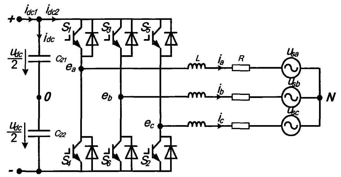
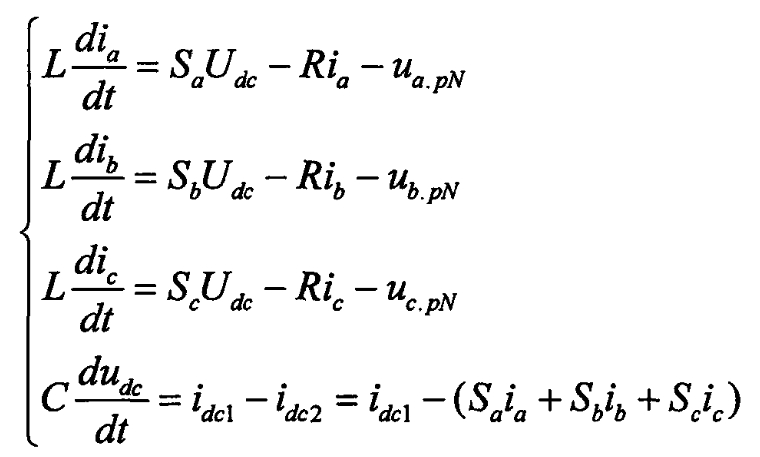
A typical three-phase voltage source solar grid connected inverter circuit is shown in the figure. It is assumed that all power devices in the diagram have ideal switching performance (resistance is equal to 0 when conducting, infinite resistance when turning off, and no delay in state switching). Under three-phase symmetrical operating conditions, according to Kirchhoff’s voltage and current laws, The following mathematical equations can be obtained as formulas. In the formula: S α 、 Sb and Sc represent the switching functions of the three bridge arms, “0” indicates that the upper bridge arm is in the off state, the lower bridge arm is in the on state, and “1” indicates the opposite; I α 、 IB and IC are the output currents of phases A, B, and C of the solar inverter; Udc is the DC side bus voltage; UapN, ubpN, and ucpN represent the voltage of phases a, b, and c at the grid connection point of the solar inverter; C21 and C22 are capacitors connected in series on a DC bus, with an equivalent capacitance of C; L. R is the equivalent inductance and resistance on the AC side.
In a three-phase three wire system, the sum of the currents in each phase is 0, that is, ia+ib+ic=0, resulting in:
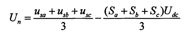
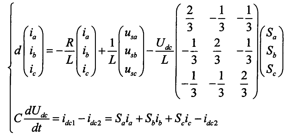
Considering the voltage symmetry of the three-phase power grid, i.e. USA+USB+USC=0, the above formula is expressed as follows:
2. Mathematical model of PWM solar inverter in synchronous rotating d-q coordinate system
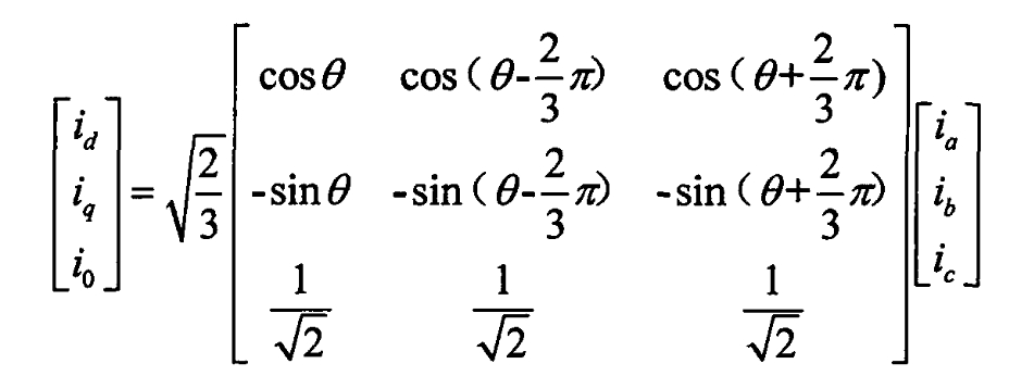
By using the “equal power” method to perform the Parker transformation, the coefficient matrix P is as follows:
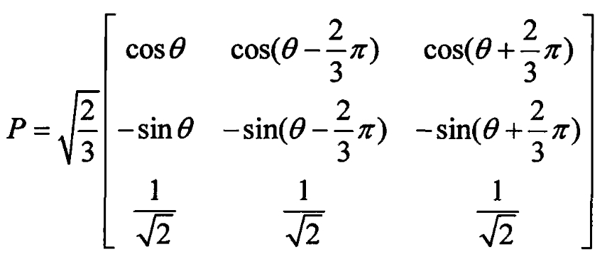
Namely:
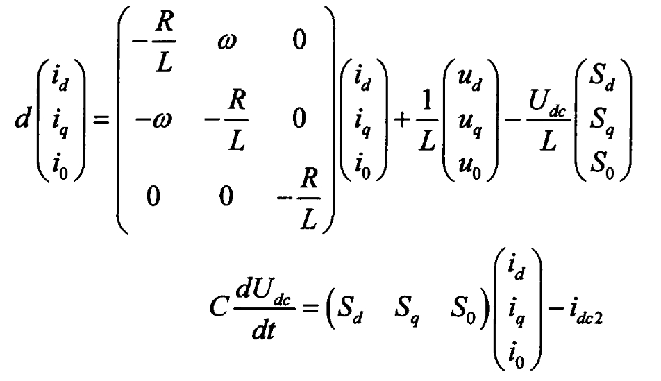
The direct current model of the solar inverter under two-phase synchronous rotation d and g coordinates can be obtained as follows:

Ud.inv is the d-axis component of the AC output voltage of the solar inverter, and Uq.inv is the q-axis component; ID is the d-axis component of the input current, and iq is the q-axis component; Md is the d-axis component of the switching function, and mq is the q-axis component; Ud is the d-axis component of the grid voltage, and Uq is the q-axis component; ω The angular velocity of the grid voltage.