
In today’s world, the escalating demand for energy resources has led to significant depletion of finite fossil fuels and exacerbated environmental pollution. This global energy crisis underscores the urgent need to develop sustainable and renewable energy sources. Solar energy, as a clean and abundant resource, has gained prominence in power generation systems. Among various applications, off-grid solar systems play a critical role in providing electricity to remote areas where traditional grid infrastructure is unavailable or impractical. This article delves into the comprehensive analysis, design, and implementation of off-grid solar systems, emphasizing their components, operational principles, challenges, and practical design methodologies. Through detailed explanations, mathematical models, and tabular data, I aim to provide a thorough understanding of how off-grid solar systems can be optimized for reliability and efficiency.
The fundamental principle of an off-grid solar system revolves around converting solar radiation into electrical energy, storing it for later use, and supplying power to loads independently of the main grid. These systems are indispensable in regions such as mountainous terrains, isolated islands, and rural communities, where grid extension is economically unfeasible. The core components include the photovoltaic (PV) array, charge controller, battery bank, and inverter. Each element must be meticulously selected and integrated to ensure seamless operation. For instance, the PV array captures sunlight and generates direct current (DC) electricity, which is then regulated by the controller to prevent battery overcharging or deep discharging. The battery bank stores excess energy for use during periods of low solar insolation, such as nights or cloudy days, while the inverter converts DC power into alternating current (AC) to run standard household appliances. The synergy among these components enables the off-grid solar system to function autonomously, making it a viable solution for electrification in off-grid locations.
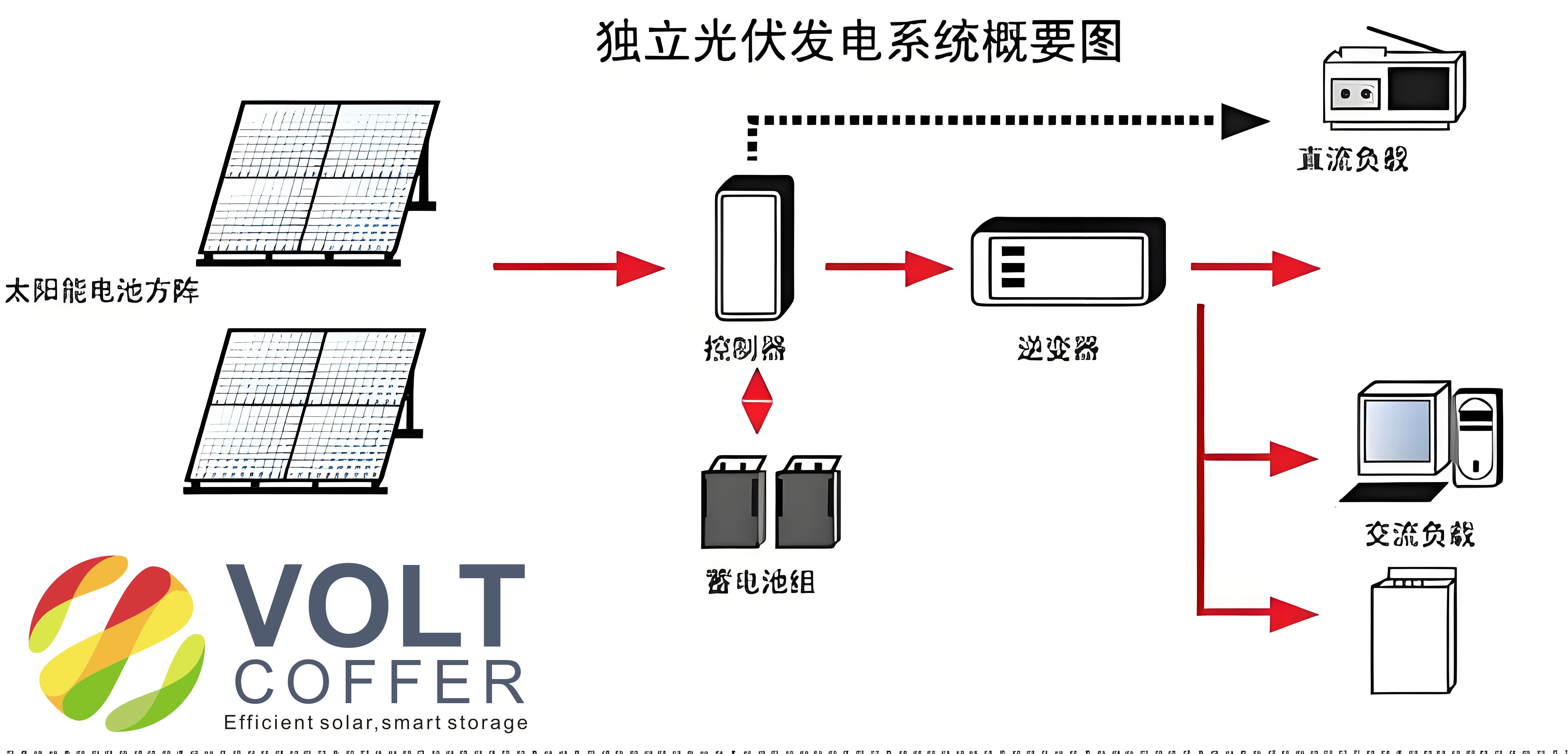
To elucidate the structure of an off-grid solar system, consider the following block diagram representation, which illustrates the interconnections and energy flow. The PV array serves as the primary energy source, with its output directed to the charge controller. The controller manages the charging and discharging cycles of the battery bank, ensuring optimal performance and longevity. Meanwhile, the inverter interfaces with the battery to supply AC power to loads. In some configurations, a backup generator may be incorporated to address extended periods of insufficient solar generation. The entire system must be designed to handle varying load demands and environmental conditions, necessitating robust engineering calculations and component sizing. Key parameters, such as system voltage, battery capacity, and PV array power, are derived based on local solar irradiance data, load profiles, and autonomy requirements. This holistic approach ensures that the off-grid solar system meets the energy needs reliably while minimizing costs and environmental impact.
The operational efficiency of an off-grid solar system hinges on the maximum power point tracking (MPPT) capability of the charge controller. The power output of a PV module is influenced by factors like solar irradiance and temperature, and it exhibits a non-linear characteristic described by the current-voltage (I-V) curve. The maximum power point (MPP) is the operating point where the product of current and voltage is maximized. Mathematically, the power \( P \) from a PV cell can be expressed as:
$$ P = V \times I $$
where \( V \) is the voltage and \( I \) is the current. The MPPT algorithm continuously adjusts the operating point to maintain peak power extraction, enhancing the overall system efficiency. For a typical silicon-based PV cell, the output under standard test conditions (STC) can be modeled using the diode equation:
$$ I = I_{ph} – I_0 \left( e^{\frac{V + I R_s}{n V_t}} – 1 \right) – \frac{V + I R_s}{R_{sh}} $$
Here, \( I_{ph} \) is the photocurrent, \( I_0 \) is the reverse saturation current, \( R_s \) is the series resistance, \( R_{sh} \) is the shunt resistance, \( n \) is the ideality factor, and \( V_t \) is the thermal voltage. Implementing MPPT in off-grid solar systems can improve energy harvest by up to 30% compared to non-MPPT controllers, making it a crucial feature for optimizing performance.
However, several challenges are associated with the deployment of off-grid solar systems. One significant issue is the battery bank’s performance and lifespan. Batteries in off-grid solar systems are subjected to frequent charge-discharge cycles, which can lead to degradation if not properly managed. The state of charge (SOC) and depth of discharge (DOD) are critical parameters that influence battery health. For example, a lead-acid battery typically has a DOD limit of 50% to avoid premature failure, whereas lithium-ion batteries can tolerate deeper discharges. The relationship between cycle life and DOD can be approximated by:
$$ N = N_0 \times \left( \frac{DOD}{DOD_0} \right)^{-k} $$
where \( N \) is the cycle life at a given DOD, \( N_0 \) is the cycle life at reference DOD \( DOD_0 \), and \( k \) is a constant dependent on battery chemistry. Additionally, temperature variations affect battery efficiency; high temperatures accelerate corrosion, while low temperatures reduce capacity. Therefore, battery selection for an off-grid solar system must consider factors like energy density, cycle life, and environmental adaptability to ensure long-term reliability.
Another challenge is the provision of backup power to handle contingencies such as prolonged cloudy weather or unexpected load increases. In off-grid solar systems, the battery bank may deplete rapidly under adverse conditions, necessitating an auxiliary power source like a diesel generator or a wind turbine. The sizing of the backup source should align with the system’s autonomy days, which represent the number of days the system can operate without solar input. The autonomy \( A \) can be calculated as:
$$ A = \frac{C_{\text{batt}} \times V_{\text{sys}} \times \text{DOD}_{\text{max}}}{E_{\text{daily}}} $$
where \( C_{\text{batt}} \) is the battery capacity in ampere-hours (Ah), \( V_{\text{sys}} \) is the system voltage, \( \text{DOD}_{\text{max}} \) is the maximum allowable depth of discharge, and \( E_{\text{daily}} \) is the average daily energy consumption in watt-hours (Wh). Incorporating a backup source requires careful integration to avoid conflicts with the existing components, and the controller must be equipped with transfer switching capabilities.
Furthermore, achieving the maximum power point is not trivial due to changing environmental conditions. Advanced MPPT techniques, such as perturb and observe (P&O) or incremental conductance (IC), are employed in off-grid solar systems to dynamically track the MPP. The P&O method involves perturbing the operating voltage and observing the change in power output. If power increases, the perturbation continues in the same direction; otherwise, it reverses. This can be summarized as:
$$ \frac{dP}{dV} > 0 \quad \text{for left of MPP}, $$
$$ \frac{dP}{dV} = 0 \quad \text{at MPP}, $$
$$ \frac{dP}{dV} < 0 \quad \text{for right of MPP}. $$
Despite its simplicity, P&O may oscillate around the MPP under rapid irradiance changes. In contrast, the IC method uses the conductance derivative to precisely locate the MPP:
$$ \frac{dI}{dV} = -\frac{I}{V} \quad \text{at MPP}. $$
These algorithms are implemented in modern charge controllers to enhance the efficiency of off-grid solar systems, ensuring that the available solar energy is utilized to its fullest potential.
In practical applications, the design of an off-grid solar system begins with a thorough assessment of the load requirements and local solar resources. For instance, consider a hypothetical project aimed at electrifying a remote community with no grid access. The first step involves cataloging all electrical loads and estimating their daily energy consumption. A sample load table is provided below:
| Load Type | Power Rating (W) | Quantity | Hours of Use per Day | Daily Energy (Wh) |
|---|---|---|---|---|
| LED Lights | 10 | 20 | 5 | 1000 |
| Fan | 50 | 10 | 4 | 2000 |
| TV | 100 | 5 | 3 | 1500 |
| Refrigerator | 150 | 5 | 24 | 18000 |
| Total | 22500 |
Based on the total daily energy requirement of 22,500 Wh, the PV array size can be determined using the formula:
$$ P_{\text{PV}} = \frac{E_{\text{daily}}}{H_{\text{peak}} \times \eta_{\text{system}}} $$
where \( P_{\text{PV}} \) is the peak power of the PV array in watts-peak (Wp), \( H_{\text{peak}} \) is the average peak sun hours per day (e.g., 5 hours), and \( \eta_{\text{system}} \) is the overall system efficiency (typically 0.7-0.8 accounting for losses). Assuming \( H_{\text{peak}} = 5 \) hours and \( \eta_{\text{system}} = 0.75 \), we get:
$$ P_{\text{PV}} = \frac{22500}{5 \times 0.75} = 6000 \, \text{Wp} $$
Thus, a 6 kWp PV array is needed. The battery capacity can be calculated considering the autonomy days. For an autonomy of 3 days and a system voltage of 48 V, with a maximum DOD of 50% for lead-acid batteries:
$$ C_{\text{batt}} = \frac{E_{\text{daily}} \times A}{V_{\text{sys}} \times \text{DOD}_{\text{max}}} = \frac{22500 \times 3}{48 \times 0.5} = 2812.5 \, \text{Ah} $$
Rounding up, a battery bank of approximately 3000 Ah at 48 V would be required. This highlights the importance of accurate sizing in off-grid solar systems to balance cost and reliability.
The selection of components for an off-grid solar system is critical to its performance. For the charge controller, key parameters include the input voltage range, maximum charging current, and MPPT efficiency. Below is a table summarizing typical specifications for a controller suitable for a medium-sized off-grid solar system:
| Parameter | Value |
|---|---|
| Rated DC Voltage | 360-800 V |
| Maximum Charging Current | 58 A |
| Maximum PV Power | 22 kWp |
| Open Circuit Voltage per String | 1000 V |
| No-Load Power Consumption | 150 mA |
| Efficiency | 98% |
| Operating Altitude | Up to 6000 m (derated above 5000 m) |
Similarly, the inverter must match the system voltage and load requirements. For a 6 kWp off-grid solar system, a 6 kVA inverter with an input voltage of 48 V DC and output of 230 V AC would be appropriate. The efficiency of the inverter, typically above 90%, directly impacts the overall system performance. Moreover, the use of a combiner box (e.g., a 4-input model) simplifies wiring between the PV array and inverter, reducing installation costs and enhancing safety. The combiner box should have a current rating sufficient to handle the maximum string currents and be rated for outdoor use with adequate ingress protection (e.g., IP65).
The orientation and tilt angle of the PV array are vital for maximizing energy capture in an off-grid solar system. The optimal tilt angle depends on the geographic latitude and seasonal sun path. A general guideline for fixed-tilt systems is to set the angle equal to the latitude for annual energy optimization. However, adjustments can be made based on seasonal load variations. The following table provides recommended tilt angles for different latitude ranges:
| Latitude Range (degrees) | Tilt Angle (degrees) |
|---|---|
| 0-25 | Equal to latitude |
| 26-40 | Latitude + 5 to 10 |
| 41-55 | Latitude + 10 to 15 |
| Above 55 | Latitude + 15 to 20 |
For example, at a latitude of 30°, the tilt angle could be set to 35° to enhance winter production. The solar azimuth angle is typically set to true south in the Northern Hemisphere. The incident solar radiation on a tilted surface can be estimated using the following equation:
$$ G_{\text{tilt}} = G_{\text{horizontal}} \times \frac{\cos(\theta)}{\sin(\alpha)} $$
where \( G_{\text{tilt}} \) is the irradiance on the tilted surface, \( G_{\text{horizontal}} \) is the horizontal irradiance, \( \theta \) is the angle of incidence, and \( \alpha \) is the solar altitude angle. Proper alignment ensures that the off-grid solar system operates at peak efficiency, reducing the required array size and cost.
Safety measures, such as grounding and lightning protection, are indispensable in off-grid solar systems to prevent equipment damage and ensure user safety. All metallic components, including PV module frames and mounting structures, must be grounded to a common earth point. The grounding resistance should be less than 10 ohms, achieved by installing electrodes in moist, non-corrosive soil. Additionally, surge protection devices (SPDs) should be installed at the DC and AC sides to mitigate voltage spikes from lightning strikes. The grounding system can be designed using the formula for earth resistance of a rod:
$$ R = \frac{\rho}{2\pi L} \ln\left(\frac{4L}{d}\right) $$
where \( R \) is the resistance in ohms, \( \rho \) is the soil resistivity in ohm-meters, \( L \) is the length of the rod in meters, and \( d \) is the diameter of the rod in meters. For instance, in soil with \( \rho = 100 \, \Omega \cdot \text{m} \), a 2-meter rod with a diameter of 0.02 meters would have a resistance of approximately 36 ohms, necessitating multiple rods in parallel to achieve the desired value. Equipotential bonding between all conductive parts further reduces the risk of electric shock and fire hazards in off-grid solar installations.
In conclusion, off-grid solar systems represent a sustainable and practical solution for electrifying remote and underserved areas. Through careful design, component selection, and implementation, these systems can provide reliable power while minimizing environmental impact. The integration of MPPT technology, robust battery management, and safety features ensures optimal performance and longevity. As solar technology advances, the efficiency and affordability of off-grid solar systems are expected to improve, further expanding their adoption. By addressing the unique challenges of off-grid applications, such as battery lifespan and energy storage, we can harness solar energy to bridge the energy access gap and promote sustainable development worldwide. The insights and methodologies discussed in this article serve as a foundation for engineers and planners to deploy effective off-grid solar solutions tailored to diverse geographical and socio-economic contexts.