
In recent years, as global awareness of energy crises has intensified, the focus on renewable energy sources has grown significantly. With the depletion of non-renewable resources like coal and oil, nations worldwide are accelerating research into sustainable alternatives. Among these, solar energy stands out due to its vast availability and broad applicability. The rapid expansion of the international photovoltaic market has spurred substantial investments in solar cell manufacturing, leading to a continuous increase in global production. For instance, in 2016, worldwide photovoltaic新增装机 capacity reached 76.6 GW, a 52.9% year-on-year growth, with China alone contributing 34.54 GW, a staggering 128.3% increase. While crystalline silicon solar cells dominate the industry, accounting for approximately 90% of the global market share due to their longevity and high conversion efficiency, there is a rising shift toward thin film solar panels. These panels, such as those based on CdTe, offer a more direct manufacturing process from raw materials to cells, bypassing the traditional silicon route. In this article, I will explore the research progress in CdTe thin film solar panels, delving into their structure, principles, material developments, and fabrication methods, while emphasizing their potential to address energy challenges.
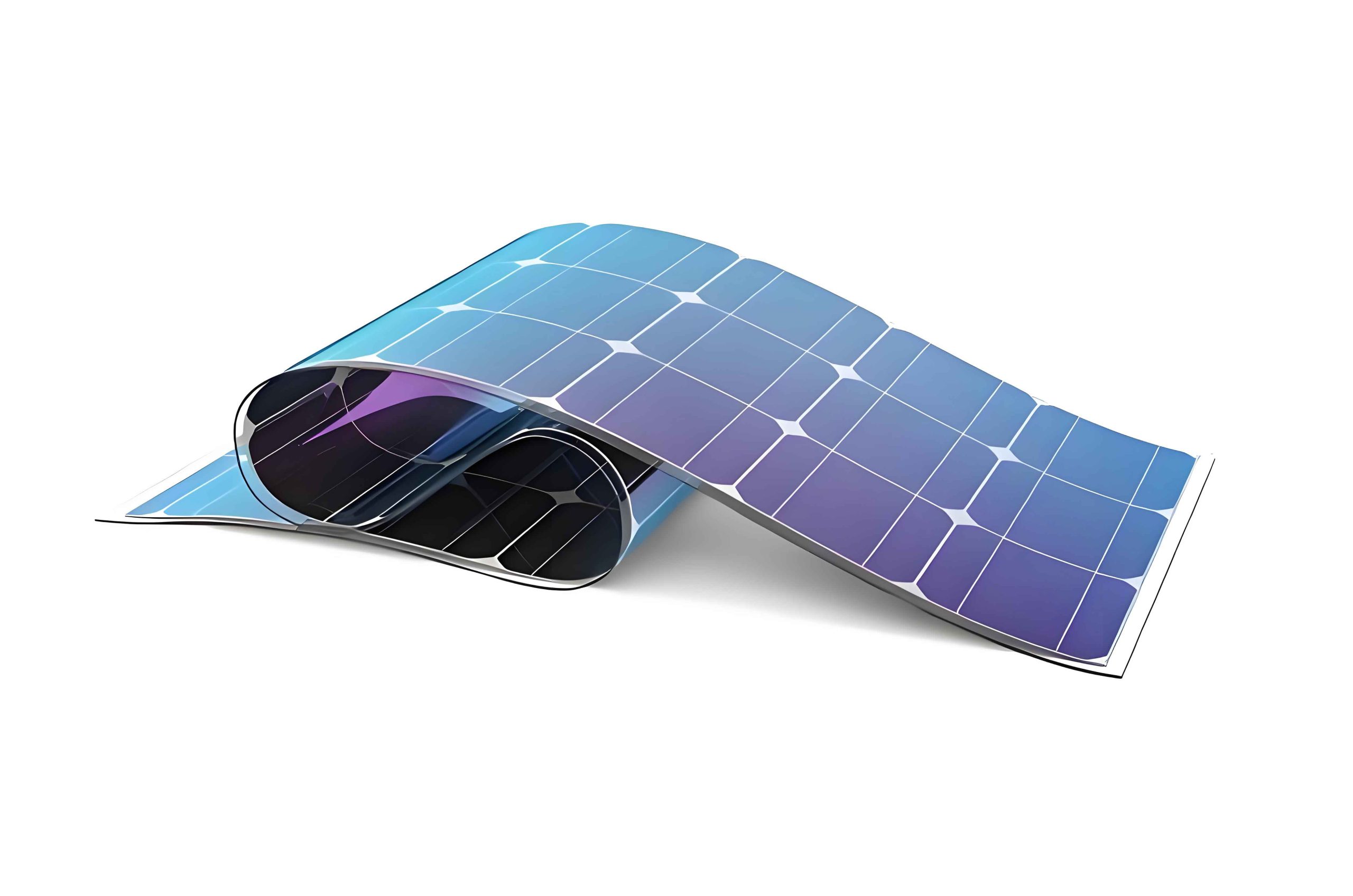
The transition to thin film solar panels is driven by their cost-effectiveness and simpler production techniques. Compared to other thin film technologies like a-Si (amorphous silicon) and CIGS (copper indium gallium selenide), CdTe thin film solar panels exhibit distinct advantages, including straightforward fabrication and lower costs. These panels are gaining traction globally, with ongoing research aimed at enhancing their conversion efficiency. As I discuss the intricacies of CdTe thin film solar panels, it is essential to understand their fundamental structure and operating principles, which underpin their performance and appeal in the renewable energy sector.
Cadmium telluride (CdTe) thin film solar panels typically employ a superstrate configuration, where light enters through a transparent glass substrate. This structure is favored for its high conversion efficiency, stable performance, and reduced manufacturing expenses. The layered design consists of several key components: a transparent conductive oxide (TCO) front electrode, a CdS window layer, a CdTe absorber layer, and a back electrode. Each layer plays a critical role in optimizing light absorption and charge carrier collection. The energy band diagram of this configuration illustrates the alignment of energy levels, facilitating efficient electron-hole pair separation and current flow. The general formula for the open-circuit voltage in such a heterojunction solar cell can be expressed as:
$$ V_{oc} = \frac{kT}{q} \ln\left(\frac{J_{ph}}{J_0} + 1\right) $$
where \( V_{oc} \) is the open-circuit voltage, \( k \) is Boltzmann’s constant, \( T \) is temperature, \( q \) is the electron charge, \( J_{ph} \) is the photocurrent density, and \( J_0 \) is the reverse saturation current density. This relationship highlights the importance of material properties in thin film solar panels.
The TCO front electrode is deposited directly onto the glass substrate, serving as both a transparent window and a conductive layer. It must exhibit high optical transparency and low electrical resistivity to maximize light ingress and minimize losses. Common TCO materials used in thin film solar panels include fluorine-doped tin oxide (FTO), indium tin oxide (ITO), aluminum-doped zinc oxide (AZO), and others. Their bandgaps typically exceed 3 eV, ensuring minimal absorption in the visible spectrum. The performance of TCO layers can be compared using parameters such as sheet resistance and transmittance, as summarized in the table below:
| TCO Material | Bandgap (eV) | Sheet Resistance (Ω/sq) | Transmittance (%) | Common Use in Thin Film Solar Panels |
|---|---|---|---|---|
| FTO | ~3.5 | 5-15 | 80-85 | Widely used due to stability |
| ITO | ~3.7 | 2-10 | 85-90 | High performance but costly |
| AZO | ~3.3 | 4-20 | 80-88 | Emerging alternative |
| ZnO:F | ~3.4 | 3-12 | 82-87 | Promising for scalability |
The CdS window layer acts as an n-type semiconductor buffer, facilitating junction formation with the p-type CdTe absorber. Despite its favorable chemical stability and transparency, CdS has a relatively narrow bandgap (~2.4 eV), leading to parasitic absorption and current loss in thin film solar panels. Researchers have explored various deposition techniques, such as chemical bath deposition (CBD), close-spaced sublimation (CSS), and physical vapor deposition (PVD), to optimize CdS thickness and quality. The optical absorption in this layer can be described by Beer-Lambert’s law:
$$ I = I_0 e^{-\alpha d} $$
where \( I \) is the transmitted intensity, \( I_0 \) is the incident intensity, \( \alpha \) is the absorption coefficient, and \( d \) is the layer thickness. Reducing \( d \) or using alternative wide-bandgap materials like CdS:O can mitigate losses, enhancing the overall efficiency of thin film solar panels.
The CdTe absorber layer is the heart of these thin film solar panels, characterized by an ideal direct bandgap of approximately 1.44 eV, which aligns well with the solar spectrum for optimal photon absorption. Its high absorption coefficient (~105 cm-1) allows for thin layers (1-3 μm), reducing material usage and cost. The photogenerated current density \( J_{ph} \) depends on the absorption profile and can be approximated by:
$$ J_{ph} = q \int_0^{\infty} \Phi(\lambda) \left[1 – e^{-\alpha(\lambda) d}\right] d\lambda $$
where \( \Phi(\lambda) \) is the photon flux at wavelength \( \lambda \), and \( \alpha(\lambda) \) is the wavelength-dependent absorption coefficient. Deposition methods for CdTe include high-temperature processes like CSS and low-temperature techniques such as electrodeposition. High-temperature deposition (above 550°C) often yields better crystallinity and efficiency in thin film solar panels, as it promotes grain growth and reduces defects.
The back electrode, typically comprising a metal layer like Ni/Al or Cu/Au, interfaces with the CdTe absorber through a buffer layer to address the high work function of CdTe and minimize contact resistance. This buffer, often made of materials like CuxTe or ZnTe:Cu, enhances ohmic contact and improves voltage output. The overall conversion efficiency \( \eta \) of thin film solar panels is a key metric, defined as:
$$ \eta = \frac{V_{oc} \times J_{sc} \times FF}{P_{in}} \times 100\% $$
where \( J_{sc} \) is the short-circuit current density, \( FF \) is the fill factor, and \( P_{in} \) is the incident solar power (typically 1000 W/m2 under standard test conditions). For CdTe thin film solar panels, record efficiencies have surpassed 22%, demonstrating their competitiveness in the photovoltaic market.
Historically, research on thin film solar panels began in the 1930s, with the first silicon solar cell developed at Bell Labs. However, interest in CdTe emerged later due to its favorable properties. Initial efforts in the mid-20th century yielded low efficiencies, but by the 1980s, conversion rates reached around 10%. In China, research on CdTe thin film solar panels started in the 1980s but stagnated until the late 1990s, when national support revived efforts, leading to significant advancements. Today, CdTe technology is a cornerstone of the thin film solar panel industry, with continuous improvements driven by material science and engineering innovations.
The fabrication of CdTe thin film solar panels employs various methods, but close-spaced sublimation (CSS) is predominant due to its simplicity, rapid deposition rates, and cost-effectiveness. In CSS, a CdTe source and substrate are placed in close proximity (2-5 mm apart) within a vacuum chamber, with temperatures controlled between 550-650°C for the substrate and 600-690°C for the source. An inert gas like nitrogen is used as a ambient to prevent oxidation. This process enables uniform film growth and high throughput, essential for commercial production of thin film solar panels. Other techniques include vapor transport deposition (VTD), magnetron sputtering, and electrochemical deposition, each with unique advantages. The table below compares these deposition methods:
| Deposition Method | Temperature Range (°C) | Deposition Rate (μm/min) | Advantages | Challenges | Suitability for Thin Film Solar Panels |
|---|---|---|---|---|---|
| Close-Spaced Sublimation (CSS) | 550-690 | 1-10 | High quality, scalable | Temperature control | Excellent for large-area panels |
| Vapor Transport Deposition (VTD) | 500-600 | 5-20 | Fast, efficient | Complex equipment | Ideal for mass production |
| Magnetron Sputtering | 200-400 | 0.1-1 | Low temperature, uniform | Slow rate, cost | Good for lab-scale research |
| Electrochemical Deposition | 50-90 | 0.05-0.2 | Low cost, ambient conditions | Lower efficiency | Promising for flexible panels |
In addition to fabrication, the performance of thin film solar panels is influenced by post-deposition treatments. For CdTe thin film solar panels, a crucial step is the cadmium chloride (CdCl2) activation process, which involves annealing the CdTe layer in the presence of CdCl2 at around 400°C. This treatment passivates grain boundaries, enhances crystallinity, and improves junction quality, boosting efficiency. The reaction can be represented as:
$$ \text{CdTe} + \text{CdCl}_2 \rightarrow \text{CdTe:Cl} + \text{volatile byproducts} $$
This chlorine incorporation reduces recombination losses, a common issue in polycrystalline thin film solar panels. Furthermore, the environmental impact of CdTe has been a topic of discussion, but lifecycle analyses show that thin film solar panels based on CdTe have a low carbon footprint and energy payback time compared to silicon counterparts. With proper recycling protocols, the use of cadmium can be managed sustainably, supporting the adoption of these thin film solar panels.
Looking at global trends, the market for thin film solar panels is expanding, driven by their lightweight, flexibility, and lower material consumption. CdTe thin film solar panels, in particular, have seen widespread deployment in utility-scale projects due to their cost competitiveness. For example, in 2023, CdTe modules accounted for over 5% of the global photovoltaic market, with projections indicating growth as efficiencies improve. The table below summarizes key performance metrics for various thin film solar panel technologies:
| Technology | Material | Average Efficiency (%) | Stability | Cost (USD/W) | Application in Thin Film Solar Panels |
|---|---|---|---|---|---|
| a-Si | Amorphous silicon | 6-8 | Moderate | 0.4-0.6 | Consumer electronics |
| CIGS | Copper indium gallium selenide | 12-14 | High | 0.5-0.8 | Building-integrated PV |
| CdTe | Cadmium telluride | 10-22 | Very High | 0.3-0.5 | Large-scale power plants |
| Perovskite | Organic-inorganic hybrid | 15-25 | Developing | 0.2-0.4 (potential) | Emerging technology |
The efficiency of thin film solar panels can be further analyzed using the detailed balance principle, as formulated by Shockley and Queisser. The theoretical maximum efficiency for a single-junction solar cell under AM1.5 illumination is around 33%, limited by bandgap and radiative recombination. For CdTe with a bandgap of 1.44 eV, the limit is approximately 32%, indicating room for improvement in current thin film solar panels. The efficiency \( \eta_{max} \) can be estimated as:
$$ \eta_{max} = \frac{\int_{E_g}^{\infty} \frac{E}{E_{ph}} \Phi(E) dE}{\int_{0}^{\infty} \Phi(E) dE} \times \left(1 – \frac{kT}{E_g} \ln\left(\frac{J_{0}}{J_{ph}}\right)\right) $$
where \( E_g \) is the bandgap energy, \( E_{ph} \) is the photon energy, and \( \Phi(E) \) is the spectral photon flux. Practical thin film solar panels often fall short due to non-radiative recombination, resistive losses, and optical losses, but ongoing research aims to bridge this gap through advanced materials and device architectures.
One promising avenue for enhancing thin film solar panels is the development of tandem structures, where CdTe is combined with other absorbers to capture a broader spectrum. For instance, a perovskite/CdTe tandem cell could leverage the high efficiency of perovskite top cells with the stability of CdTe bottom cells. The current matching condition in such tandem thin film solar panels is critical and can be expressed as:
$$ J_{top} = J_{bottom} $$
where \( J_{top} \) and \( J_{bottom} \) are the photocurrent densities of the top and bottom subcells, respectively. By optimizing layer thicknesses and bandgaps, tandem thin film solar panels could achieve efficiencies exceeding 30%, pushing the boundaries of photovoltaic technology.
Moreover, the scalability of CdTe thin film solar panels is facilitated by roll-to-roll manufacturing processes, which enable continuous production on flexible substrates. This approach reduces costs and energy consumption, making thin film solar panels more accessible for diverse applications, from rooftop installations to portable devices. The economic viability can be assessed using the levelized cost of electricity (LCOE), given by:
$$ \text{LCOE} = \frac{\sum_{t=1}^{n} \frac{I_t + M_t}{(1+r)^t}}{\sum_{t=1}^{n} \frac{E_t}{(1+r)^t}} $$
where \( I_t \) is the investment cost in year \( t \), \( M_t \) is the maintenance cost, \( E_t \) is the energy output, \( r \) is the discount rate, and \( n \) is the lifetime. Thin film solar panels often exhibit lower LCOE than crystalline silicon in large-scale deployments, underscoring their potential in the energy transition.
In conclusion, CdTe thin film solar panels represent a vital technology in the pursuit of sustainable energy solutions. With their ideal bandgap, high absorption, and cost-effective production, they offer a compelling alternative to traditional solar cells. As research continues to address challenges such as material toxicity and efficiency ceilings, the future of thin film solar panels looks bright. I believe that by investing in innovation and scaling up manufacturing, CdTe thin film solar panels can play a pivotal role in mitigating climate change and securing our energy future. The journey from laboratory breakthroughs to widespread adoption underscores the dynamic nature of this field, and I am optimistic that thin film solar panels will continue to evolve, driving the global transition to renewable energy.