
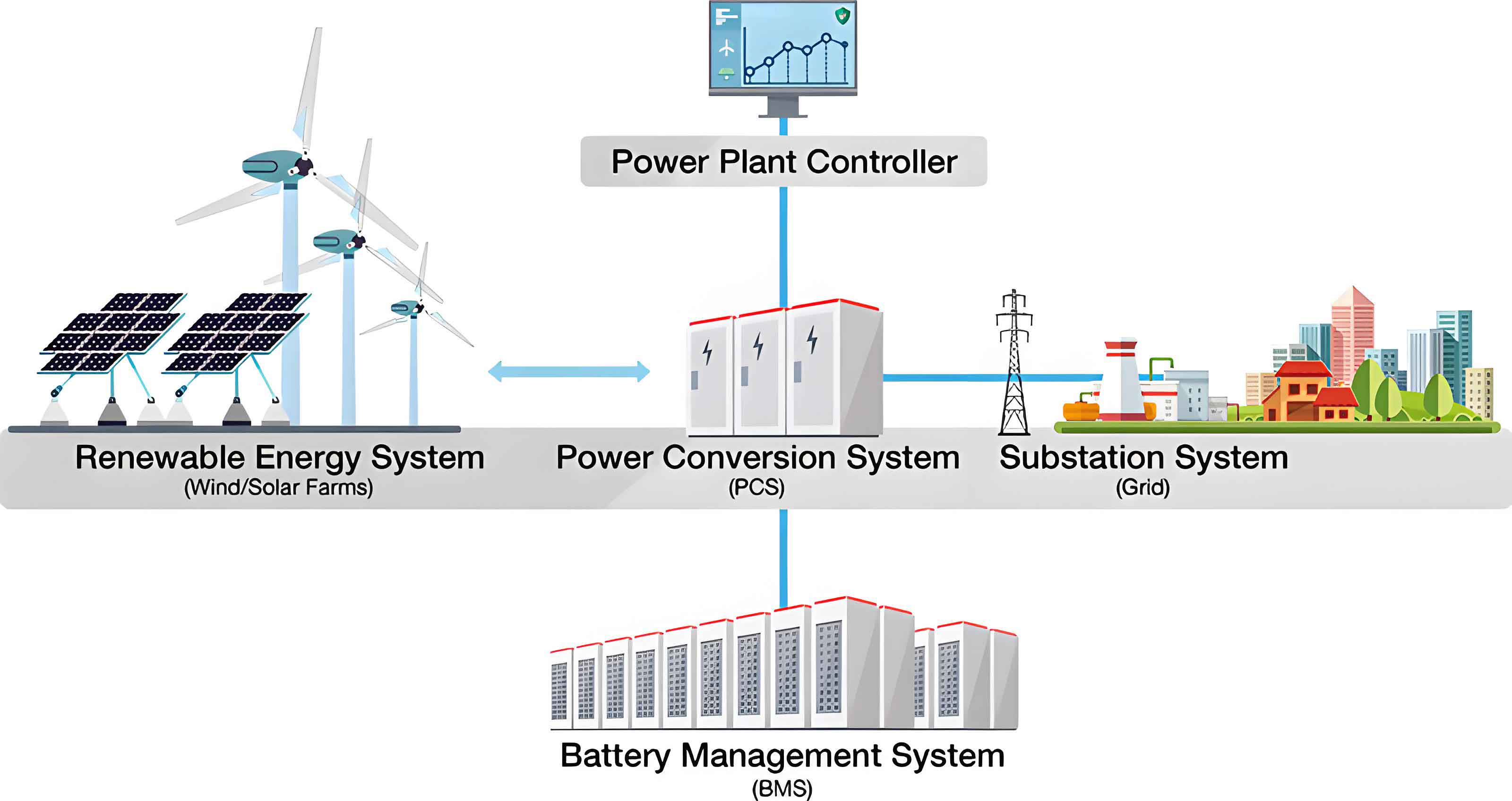
The global transition towards carbon neutrality has propelled the rapid deployment of renewable energy sources like wind and solar. Their inherent intermittency, however, necessitates robust energy storage solutions to ensure grid stability and reliability. Among various technologies, electrochemical energy storage, particularly Lithium-ion Battery Energy Storage Systems (BESS), has become the dominant force due to its high energy density, long cycle life, and decreasing cost. BESS are now pivotal in applications ranging from grid frequency regulation and peak shaving to integrating distributed renewable generation.
Despite their advantages, the large-scale application of BESS is shadowed by significant safety concerns. Under abusive conditions such as overcharging, external heating, or internal short circuits, lithium-ion batteries can undergo a violent, self-accelerating exothermic chain reaction known as thermal runaway (TR). This process can lead to cell venting, fire, jet flames, and even explosion. Within a densely packed battery energy storage system, a single cell’s TR can propagate to neighboring cells through heat transfer, potentially escalating into a catastrophic module- or container-level fire event. Such incidents pose severe risks to personnel, infrastructure, and grid operations, as evidenced by several high-profile fires in recent years. Therefore, the development of reliable early detection technologies for incipient TR and effective safety mitigation strategies is paramount for the sustainable and safe expansion of battery energy storage system deployments.
1. Fundamentals of Thermal Runaway in Energy Storage Batteries
Understanding the fundamental processes leading to TR is the cornerstone for developing effective detection and mitigation strategies. For grid-scale battery energy storage system installations, lithium iron phosphate (LFP) cathodes are widely preferred over higher-energy-density nickel-manganese-cobalt (NMC) oxides due to their superior thermal and chemical stability. However, LFP batteries are not immune to TR under extreme conditions.
1.1 Triggers and Internal Reaction Cascade
TR in a lithium-ion cell can be initiated by three primary abuse conditions: thermal abuse (e.g., external heating, ambient overheating), electrical abuse (e.g., overcharge, over-discharge, short circuit), and mechanical abuse (e.g., crush, penetration). In the context of a stationary battery energy storage system, thermal and electrical abuses are the most common operational hazards.
The core mechanism behind TR is a thermo-chemical positive feedback loop. Heat generated from any trigger (e.g., joule heating from an internal short circuit) raises the cell’s internal temperature, which in turn accelerates exothermic side reactions. The heat from these reactions further increases temperature, creating a runaway condition. The key sequential internal reactions for a typical LFP/graphite cell are as follows:
1. Solid Electrolyte Interphase (SEI) Decomposition (~90-120 °C): The metastable SEI layer on the graphite anode decomposes, exposing the highly reactive lithiated carbon to the electrolyte.
$$ (CH_2OCO_2Li)_2 \rightarrow Li_2CO_3 + C_2H_4 + CO_2 + \frac{1}{2}O_2 $$
2. Reaction between Anode and Electrolyte (~120-200 °C): The exposed lithiated graphite reacts exothermically with the organic carbonate electrolyte (e.g., Ethylene Carbonate – EC, Diethyl Carbonate – DEC).
$$ 2Li + C_3H_4O_3(EC) \rightarrow Li_2CO_3 + C_2H_4 $$
$$ 2Li + C_5H_{10}O_3(DEC) \rightarrow Li_2CO_3 + C_4H_{10} $$
3. Cathode Decomposition and Electrolyte Oxidation (~180-250 °C): The delithiated cathode material (e.g., FePO₄ from LFP) can react with the electrolyte, releasing oxygen and heat. Simultaneously, electrolyte solvents decompose.
$$ (1-x)LiFePO_4 + xFePO_4 \rightarrow \frac{1- x}{2}LiFePO_4 + \frac{x}{4}Fe_2P_2O_7 + \frac{x}{4}O_2 $$
$$ EC + 2.5O_2 \rightarrow 3CO_2 + 2H_2O $$
4. Binder Decomposition (~250 °C and above): The polyvinylidene fluoride (PVDF) binder can react with lithium or decompose.
$$ -CH_2-CF_2- \rightarrow -CH=CF- + HF $$
This chain reaction leads to a massive, rapid release of heat and gas, causing a sharp temperature spike, pressure build-up, venting, and often ignition of the ejected flammable gases.
1.2 Evolution of External Characteristic Parameters
The internal reaction cascade manifests through measurable external parameters. Monitoring these parameters forms the basis for most state detection and early warning systems in a battery energy storage system.
1.2.1 Temperature
Temperature is the most direct indicator of thermal behavior. The TR process can be characterized by three critical temperature points (θ₁, θ₂, θ₃) dividing it into four stages: onset of self-heating (θ₁), thermal runaway trigger (θ₂), temperature peak (θ₃), and cooling. For LFP cells, θ₁ typically occurs below 100°C, θ₂ between 100-200°C, and θ₃ can exceed 500°C. The rate of temperature rise (dT/dt) is a crucial warning signal. A significant increase in dT/dt, often with a threshold like >1°C/s over a 30-second interval, can indicate the transition from normal self-heating to uncontrollable TR.
1.2.2 Voltage
Voltage behavior depends on the abuse mode. During overcharge-induced TR, voltage rises steadily until the internal short circuit causes a sudden collapse to near zero. Under external heating, voltage remains relatively stable until the separator melts, leading to an internal short and a subsequent voltage drop. Anomalous voltage fluctuations, early voltage drop during charging, or significant deviation from the pack average can be early signs of internal faults like micro-shorts.
1.2.3 Gas Generation
Gas generation is an early and sensitive indicator, often preceding significant temperature rise and voltage drop. The composition evolves with temperature:
- Early Stage (SEI/Anode reactions): CO₂, CO, C₂H₄ (ethylene), H₂.
- Mid Stage (Electrolyte decomposition): Increased CO, CO₂, along with other hydrocarbons (CH₄, C₂H₆).
- Late Stage (Combustion/Venting): A complex mixture including HF (from LiPF₆ salt decomposition), POF₃, and soot.
Hydrogen (H₂) is particularly noteworthy as it is generated from reactions between lithium plating/dendrites and the binder or electrolyte at relatively early stages, making it a promising target for early warning.
The table below summarizes the characteristic evolution of these parameters during a typical heating-induced TR event.
| TR Stage | Internal Process | Temperature | Voltage | Key Gases Released |
|---|---|---|---|---|
| Stage 1: Self-heating | SEI decomposition begins | Gradual rise (>θ₁) | Stable | Trace CO₂, CO, C₂H₄ |
| Stage 2: Trigger | Anode-Electrolyte reaction, separator melt | Rapid rise (θ₂ reached) | Begins to drop | H₂, CO, hydrocarbons increase |
| Stage 3: Runaway | Cathode decomp., electrolyte combustion | Sharp peak (θ₃) | Collapses to ~0 V | Large volume: CO₂, CO, HF, smoke |
| Stage 4: Propagation | Heat transfer to adjacent cells | High, then cools | N/A (failed cell) | Combustion products |
2. Thermal Runaway State Detection Technologies
Conventional battery energy storage system monitoring relies on a Battery Management System (BMS) measuring voltage, current, and surface temperature. While essential, these methods often detect TR only at a late stage (e.g., after venting or fire has started). Advanced detection aims to provide earlier warnings by leveraging more sensitive or internal parameters.
2.1 Sensor-Based Detection Strategies
2.1.1 External (Non-Invasive) Sensing
This involves placing sensors on or near the cell exterior.
- Voltage & Temperature Analytics: Moving beyond simple threshold alarms, model-based and data-driven approaches are used. Model-based methods use estimators (e.g., Kalman Filters) to predict normal voltage/temperature and flag residuals. Data-driven methods employ machine learning (e.g., Convolutional Neural Networks – Long Short-Term Memory networks) to learn normal patterns from historical BMS data and detect subtle anomalies predictive of failure.
- Gas Sensing: Deploying gas sensors (for H₂, CO, CO₂, HF) within the battery enclosure or module can provide very early warning. H₂ sensors, in particular, have shown promise in detecting faults minutes before smoke or fire appears. Challenges include sensor cross-sensitivity, longevity in harsh environments, and placement optimization for rapid gas detection.
- Multi-Parameter Fusion: Combining voltage, temperature, and gas data with intelligent algorithms (e.g., fuzzy logic, Bayesian networks) significantly reduces false alarms and improves detection reliability. For instance, a minor temperature rise coupled with a specific gas signature (e.g., H₂ spike) is a stronger indicator of an early anode fault than any single parameter.
2.1.2 Internal (Invasive or Semi-Invasive) Sensing
To overcome the lag in external measurements, sensors can be integrated into the cell.
- Micro-Sensors: Thin-film micro-sensors for temperature and pressure can be embedded on current collectors or separators. They offer faster and more accurate internal temperature response than surface thermocouples.
- Fiber Bragg Grating (FBG) Sensors: Optical fiber sensors are immune to electromagnetic interference and can measure both internal temperature and strain/pressure in real-time. They have been successfully implanted into cells, providing critical data during TR, such as the precise moment of separator failure and internal pressure surge.
The table below compares the main sensing approaches.
| Sensing Approach | Measurands | Advantages | Disadvantages/Challenges |
|---|---|---|---|
| External BMS | Voltage, Surface Temp, Current | Standard, non-invasive, cost-effective | Late detection, surface temp lags core temp |
| External Gas | H₂, CO, CO₂, HF concentrations | Very early warning potential | Sensor drift, cross-sensitivity, placement optimization |
| Internal Micro-sensors | Internal Temp, Pressure | Fast, accurate internal state data | Invasive, may affect cell integrity, manufacturing complexity |
| Internal FBG Sensors | Internal Temp, Strain | EMI immune, multi-point sensing, excellent for R&D | High cost, fragile, complex integration for mass production |
2.2 Electrochemical Impedance Spectroscopy (EIS)
EIS is a powerful non-invasive diagnostic tool that probes the internal electrochemical state of a cell by applying a small AC current/voltage over a range of frequencies and measuring the impedance response. The impedance spectrum can be modeled by an equivalent circuit with elements representing ohmic resistance (RΩ), charge transfer resistance (Rct), double-layer capacitance (Cdl), and Warburg diffusion impedance (Zw).
$$ Z(\omega) = R_\Omega + \frac{R_{ct}}{1 + j \omega R_{ct} C_{dl}} + Z_w(\omega) $$
Changes in cell state (SOC, SOH, temperature) affect these parameters. For TR warning:
- Internal Temperature Estimation: The phase shift (θ) of the impedance at mid-frequencies (e.g., 10-100 Hz) has a strong, relatively SOC/SOH-independent correlation with internal temperature. Online single-frequency impedance measurement can thus be used for real-time core temperature monitoring.
- Early Fault Detection: The onset of lithium plating or internal short circuits alters the impedance spectrum. Tracking the dynamic impedance at a specific frequency (e.g., 70 Hz) can reveal characteristic “knees” or slope changes that serve as precursors to TR, providing warnings tens of seconds to minutes in advance.
The main challenge for online EIS in a battery energy storage system is the measurement time and the need for cell quiet periods, which is being addressed by advanced rapid EIS techniques and dynamic impedance analysis.
2.3 Ultrasonic Detection
This emerging technique uses ultrasonic waves transmitted through the cell. Changes in the cell’s internal mechanical properties (e.g., gas formation, electrode swelling, porosity) affect the speed of sound (time-of-flight – TOF) and attenuation (amplitude) of the ultrasonic signal.
- Gas Detection: The formation of even small amounts of gas during early TR stages creates strong ultrasonic scattering, causing a significant drop in signal amplitude. This is highly sensitive and can detect gas generation before it reaches external sensors.
- State Monitoring: Ultrasound can also monitor SOC (via electrode modulus changes) and SOH (via gradual structural changes), providing complementary health data.
Its non-invasive nature and high sensitivity to gas make it a promising complement to other methods, though interpreting signals requires sophisticated algorithms to decouple various influencing factors.
3. Safety Mitigation Technologies for BESS
Detection must be coupled with effective mitigation to prevent a single cell event from cascading into a system-level disaster. Safety strategies in a battery energy storage system are multi-layered.
3.1 Thermal Propagation Inhibition
The primary goal is to prevent or delay heat transfer from a TR cell to its neighbors, breaking the propagation chain.
- Cell & Module Design: Increasing inter-cell spacing, using thermal barriers (e.g., ceramic sheets, aerogels), and integrating phase change materials (PCMs) into modules absorb excess heat and isolate faulty cells.
- Thermal Management System (TMS) Enhancement: While TMS (liquid/air cooling) is designed for operational temperature control, it can be leveraged for safety. Upon TR detection, the TMS can switch to maximum cooling capacity to extract heat from adjacent cells. Advanced designs integrate insulation with liquid cooling plates for synergistic propagation suppression.
3.2 Fire Suppression and Extinguishing
When TR leads to fire, rapid suppression is critical. The choice of agent is crucial as lithium-ion fires are chemical and thermal hazards.
| Suppressant Type | Example Agents | Mechanism | Pros & Cons for BESS |
|---|---|---|---|
| Water-based | Water Mist, Fine Water Spray | Cooling, oxygen displacement, radiant heat blocking | Pros: Excellent cooling, cheap, non-toxic. Cons: Conductivity risk, water damage, may not penetrate module. |
| Chemical Gas | Perfluorohexanone (Novec 1230), HFC-227ea (FM200) | Chemical interference with combustion chain reaction, mild cooling | Pros: Clean, non-conductive, good for enclosed spaces. Cons: Poor cooling, toxic decomposition products (HF), high cost. |
| Inert Gas | CO₂, Nitrogen (N₂) | Oxygen dilution (suffocation) | Pros: No residue. Cons: Very poor cooling, high risk of reignition, asphyxiation hazard. |
| Aerosol | Condensed Aerosol Generators | Chemical radical quenching | Pros: Compact, no pressure vessels. Cons: Corrosive residue, hot deployment, obscures vision. |
The trend is towards hybrid systems combining the rapid fire knockdown of a gas agent with the sustained cooling of water mist to prevent reignition—a critical factor for lithium-ion battery fires.
3.3 System-Level Mitigation Architecture
Modern battery energy storage system design employs a hierarchical, multi-zone approach:
- Cell-Level: Passive safety devices like Current Interrupt Devices (CID), Positive Temperature Coefficient (PTC) devices, and venting mechanisms.
- Module-Level: Distributed fire extinguishing lines (e.g., nozzles for gas or mist) targeting each module, coupled with thermal barriers. “Self-triggering” fire suppression pills that activate upon exposure to high heat from a venting cell are also being developed.
- Rack/Container-Level: Centralized or zoned deluge systems (water mist or gas). Advanced designs feature “distributed” systems that can target a single rack or zone instead of flooding the entire container, minimizing damage and cost.
An intelligent control system integrates detection inputs (BMS, gas, temperature) to make informed decisions, such as disconnecting the affected string via DC contactors, activating specific zone suppression, and alerting operators.
| Mitigation Level | Typical Techniques | Objective |
|---|---|---|
| Cell-level | CID, PTC, Vent | Contain/terminate event within the cell |
| Module-level | Thermal barriers, PCM, distributed extinguisher lines | Inhibit propagation to adjacent cells/modules |
| Rack/Container-level | Zoned gas/water mist suppression, exhaust venting | Extinguish fire, control gases, protect assets |
| System-level | String disconnection, grid isolation, emergency protocols | Ensure electrical safety and operational response |
4. Conclusions and Future Perspectives
The safe operation of large-scale Lithium-ion battery energy storage system hinges on a robust, multi-faceted strategy encompassing early detection and decisive mitigation. While conventional BMS monitoring provides a foundation, it is insufficient for early TR warning. Significant progress has been made in advanced sensing (gas, internal, impedance, ultrasonic) and intelligent data analytics to identify precursors. Similarly, safety design has evolved from simple container-level sprinklers to integrated, multi-zone systems combining propagation inhibition with hybrid suppression agents.
However, challenges remain. Future research and development should focus on:
- Fundamental Understanding: Deeper in-situ and operando studies of the internal physicochemical evolution during early-stage TR to identify more definitive, early-onset signatures.
- Advanced Sensing Integration: Developing cost-effective, reliable internal sensors (like robust FBG systems) for mass production and fusing multi-modal data (voltage, acoustic, gas, impedance) with AI for highly reliable, low false-alarm-rate prognostic algorithms.
- Material & Design Innovations: Pursuing inherently safer cell chemistries (e.g., solid-state batteries) and designing modules with “built-in” firewalls and cooling paths that inherently arrest propagation.
- Standardization and Testing: Establishing industry-wide standards for TR detection system performance (e.g., required warning time) and mitigation system efficacy (e.g., propagation delay time, reignition prevention) under realistic battery energy storage system conditions.
- System-Level Digital Twins: Creating high-fidelity digital replicas of BESS that integrate thermal, electrical, and chemical models to simulate fault progression and optimize detection logic and mitigation response in-silico before deployment.
By addressing these areas, the industry can move towards battery energy storage system that are not only highly efficient and cost-effective but also demonstrably safe, thereby unlocking their full potential in building a resilient and sustainable energy infrastructure.