
As an engineer deeply involved in renewable energy technologies, I have dedicated significant effort to designing and optimizing off grid solar system solutions. These systems are crucial for providing reliable power in remote areas, and their protection mechanisms are paramount to ensuring safety and efficiency. In this article, I will explore the intricacies of a comprehensive off grid solar system protection framework, drawing from my experiences and technical insights. The core of this discussion revolves around the integration of various components that collectively safeguard the system from faults, voltage fluctuations, and other operational hazards. Throughout this exploration, I will emphasize the importance of each element in maintaining the stability of an off grid solar system, using mathematical models and empirical data to illustrate key points. By the end, readers will gain a thorough understanding of how to implement robust protection strategies for any off grid solar system deployment.
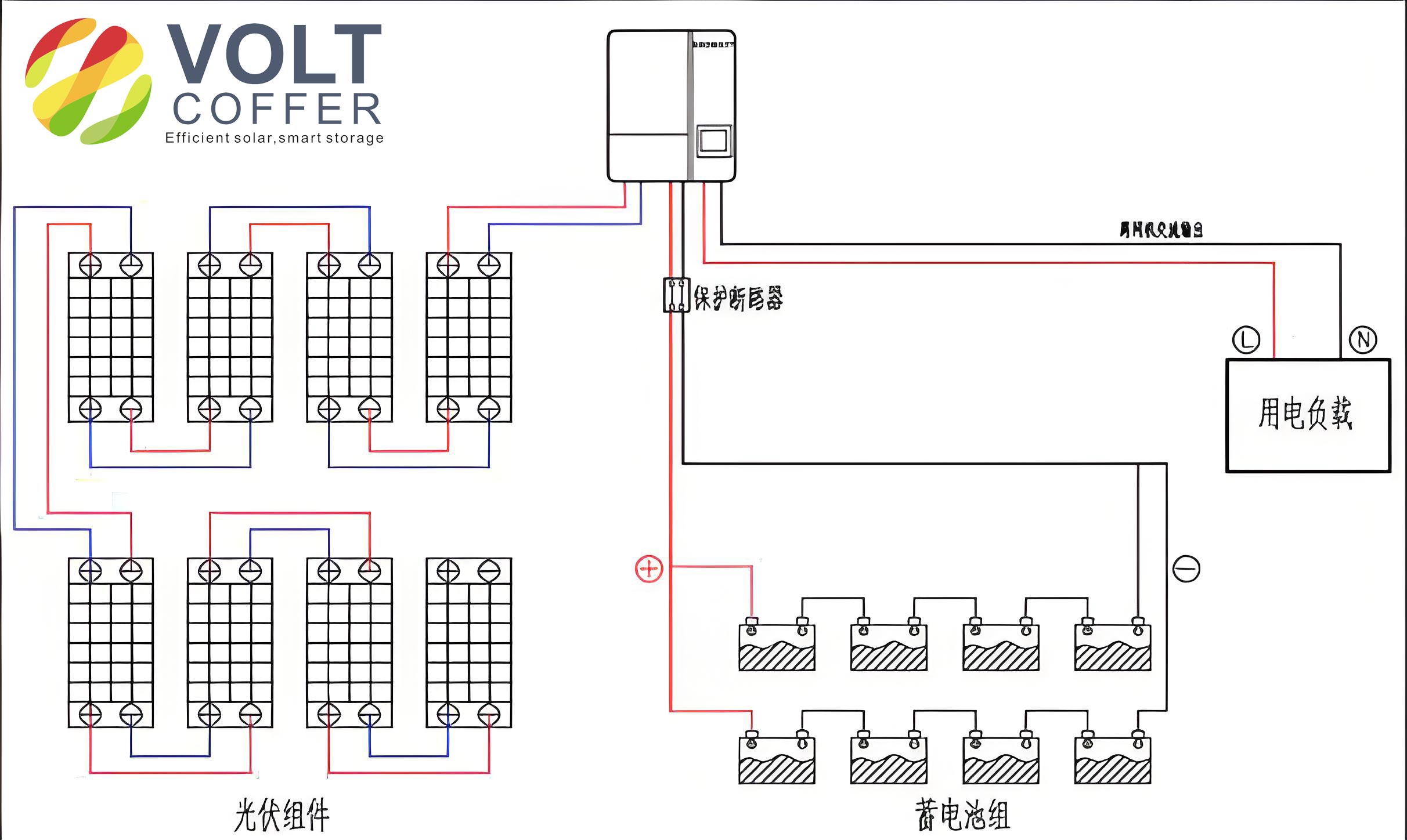
To begin, let me outline the fundamental architecture of a typical off grid solar system. This system primarily consists of distributed photovoltaic components, voltage detection devices, circuit breakers, a photovoltaic controller, a battery bank, a photovoltaic inverter, DC loads, and AC loads, all interconnected via electrical wiring. The distributed photovoltaic components capture solar energy and convert it into electrical power, which is then managed and distributed through the system. Voltage detection devices monitor the system for any anomalies, while circuit breakers provide rapid disconnection in case of faults. The photovoltaic controller regulates the charging and discharging of the battery bank, ensuring optimal energy storage. The inverter converts DC power to AC power for AC loads, and DC loads are directly powered from the DC side. This integrated approach is essential for the resilience of an off grid solar system, as it prevents damage to components and ensures continuous power supply even in challenging environments.
In my design, the distributed photovoltaic components form the heart of the off grid solar system. These components include solar cell silicon wafers and a microcontroller unit (MCU) that optimizes energy harvesting. The MCU continuously adjusts the operating points to maximize power output based on environmental conditions. For instance, the power output of a photovoltaic module can be modeled using the following equation: $$P = V \times I$$ where \(P\) is the power in watts, \(V\) is the voltage in volts, and \(I\) is the current in amperes. Additionally, the efficiency of the solar cells can be expressed as: $$\eta = \frac{P_{\text{output}}}{P_{\text{input}}} \times 100\%$$ where \(\eta\) is the efficiency, \(P_{\text{output}}\) is the electrical power output, and \(P_{\text{input}}\) is the solar irradiance incident on the panels. This efficiency is critical for the overall performance of the off grid solar system, as higher efficiency means more energy is available for storage and consumption.
The voltage detection装置 in my off grid solar system plays a vital role in monitoring system health. It comprises a sensitive galvanometer, detection circuits, and feedback circuits that work together to identify voltage sags, surges, or other irregularities. When the voltage deviates from the nominal range, the feedback circuit triggers corrective actions, such as disconnecting loads or adjusting the inverter output. The voltage detection process can be described by the transfer function: $$H(s) = \frac{V_{\text{out}}(s)}{V_{\text{in}}(s)}$$ where \(H(s)\) is the system’s transfer function in the Laplace domain, \(V_{\text{out}}(s)\) is the output voltage, and \(V_{\text{in}}(s)\) is the input voltage. This ensures that the off grid solar system remains within safe operating limits, preventing potential damage to sensitive components like batteries and inverters.
Next, the circuit breaker in my off grid solar system includes auxiliary contacts, shunt trip coils, and undervoltage trip coils, which enable rapid isolation of faulty sections. The breaker’s operation is based on the principles of electromagnetic tripping, where excessive current or voltage drops activate the trip mechanism. The tripping current can be calculated using: $$I_{\text{trip}} = k \times I_{\text{rated}}$$ where \(I_{\text{trip}}\) is the tripping current, \(k\) is a constant dependent on the breaker type, and \(I_{\text{rated}}\) is the rated current. This protection is indispensable for an off grid solar system, as it minimizes the risk of fire or equipment failure during overload conditions.
The photovoltaic controller is another critical component in my off grid solar system, featuring a control panel with input switches for photovoltaic, battery, and AC sources. This controller manages the energy flow between the solar panels, battery bank, and loads, employing maximum power point tracking (MPPT) algorithms to optimize efficiency. The MPPT algorithm can be represented by the equation: $$\frac{dP}{dV} = 0$$ where \(P\) is the power and \(V\) is the voltage, indicating the point of maximum power transfer. Additionally, the battery charging process follows a multi-stage protocol, which can be summarized in the table below:
| Charging Stage | Voltage Range (V) | Current (A) | Description |
|---|---|---|---|
| Bulk | 14.2 – 14.6 | Maximum | Rapid charging until voltage threshold |
| Absorption | 14.2 – 14.6 | Decreasing | Voltage constant, current tapers |
| Float | 13.2 – 13.8 | Low | Maintenance charging to prevent overcharge |
This table highlights how the controller ensures the longevity of the battery bank in an off grid solar system, which is essential for reliable energy storage.
Moving on, the photovoltaic inverter in my off grid solar system consists of a boost converter and an inverter bridge circuit. The boost converter steps up the DC voltage from the panels or batteries, while the inverter bridge converts it to AC power. The output voltage of the boost converter can be derived from: $$V_{\text{out}} = \frac{V_{\text{in}}}{1 – D}$$ where \(V_{\text{out}}\) is the output voltage, \(V_{\text{in}}\) is the input voltage, and \(D\) is the duty cycle of the switching signal. For the inverter bridge, the output AC voltage waveform is typically sinusoidal, represented as: $$V_{\text{ac}}(t) = V_{\text{peak}} \sin(2\pi f t)$$ where \(V_{\text{peak}}\) is the peak voltage and \(f\) is the frequency. This conversion process is vital for powering AC loads in an off grid solar system, and its efficiency directly impacts overall system performance.
To further illustrate the operational dynamics of an off grid solar system, I have developed a mathematical model that integrates all components. The overall system efficiency can be expressed as: $$\eta_{\text{system}} = \eta_{\text{pv}} \times \eta_{\text{controller}} \times \eta_{\text{battery}} \times \eta_{\text{inverter}}$$ where each \(\eta\) represents the efficiency of the respective component. For example, typical values might be \(\eta_{\text{pv}} = 0.18\), \(\eta_{\text{controller}} = 0.95\), \(\eta_{\text{battery}} = 0.85\), and \(\eta_{\text{inverter}} = 0.90\), resulting in \(\eta_{\text{system}} \approx 0.13\) or 13%. This underscores the importance of optimizing each part to enhance the overall off grid solar system efficiency.
In terms of load management, my off grid solar system handles both DC and AC loads seamlessly. DC loads, such as LED lights or DC motors, are connected directly to the battery bank or controller, while AC loads, like household appliances, rely on the inverter. The power demand for loads can be analyzed using: $$P_{\text{total}} = P_{\text{DC}} + P_{\text{AC}}$$ where \(P_{\text{DC}}\) is the power for DC loads and \(P_{\text{AC}}\) is the power for AC loads. To ensure balance, I often use a load profiling table, as shown below, which helps in sizing the system components appropriately for an off grid solar system:
| Load Type | Power Rating (W) | Daily Usage (hours) | Energy Consumption (Wh/day) |
|---|---|---|---|
| DC Light | 10 | 6 | 60 |
| AC Fan | 50 | 4 | 200 |
| Refrigerator | 100 | 24 | 2400 |
| Water Pump | 200 | 2 | 400 |
This table aids in designing an off grid solar system that meets specific energy needs without overloading the components.
Another key aspect of my off grid solar system is the protection coordination between the voltage detection device and the circuit breaker. When a fault is detected, the response time must be swift to prevent cascading failures. The fault current can be modeled using: $$I_{\text{fault}} = \frac{V_{\text{system}}}{Z_{\text{total}}}$$ where \(I_{\text{fault}}\) is the fault current, \(V_{\text{system}}\) is the system voltage, and \(Z_{\text{total}}\) is the total impedance. The breaker’s tripping time can be approximated by: $$t_{\text{trip}} = \frac{k}{I_{\text{fault}}^2}$$ where \(t_{\text{trip}}\) is the tripping time and \(k\) is a constant. This ensures that the off grid solar system remains protected under various fault conditions.
Furthermore, the battery bank in my off grid solar system is designed for deep-cycle applications, with a focus on cycle life and depth of discharge (DoD). The capacity of the battery can be calculated as: $$C = \frac{E_{\text{daily}}}{\text{DoD} \times \eta_{\text{battery}}}$$ where \(C\) is the battery capacity in ampere-hours (Ah), \(E_{\text{daily}}\) is the daily energy consumption in watt-hours (Wh), and DoD is the depth of discharge (e.g., 0.5 for 50%). For instance, if \(E_{\text{daily}} = 5000\) Wh, DoD = 0.5, and \(\eta_{\text{battery}} = 0.85\), then \(C \approx \frac{5000}{0.5 \times 0.85} \approx 11765\) Wh or about 980 Ah for a 12V system. This calculation is fundamental for sizing the battery bank in an off grid solar system to ensure autonomy during periods of low solar insolation.
In addition to component-level details, I have incorporated advanced control strategies into my off grid solar system to enhance reliability. For example, the photovoltaic controller uses pulse-width modulation (PWM) or MPPT techniques to regulate charging. The PWM duty cycle can be expressed as: $$D = \frac{T_{\text{on}}}{T_{\text{period}}}$$ where \(D\) is the duty cycle, \(T_{\text{on}}\) is the on-time, and \(T_{\text{period}}\) is the total period of the switching signal. This allows for precise control over the energy flow, which is crucial for maintaining the health of the battery bank in an off grid solar system.
To evaluate the economic viability of an off grid solar system, I often perform a cost-benefit analysis that includes the levelized cost of energy (LCOE). The LCOE can be computed using: $$\text{LCOE} = \frac{\sum_{t=1}^{n} \frac{I_t + M_t}{(1 + r)^t}}{\sum_{t=1}^{n} \frac{E_t}{(1 + r)^t}}$$ where \(I_t\) is the investment cost in year \(t\), \(M_t\) is the maintenance cost, \(E_t\) is the energy generated, \(r\) is the discount rate, and \(n\) is the system lifetime. This formula helps in comparing the off grid solar system with other power sources, highlighting its long-term benefits.
Moreover, the integration of energy storage in an off grid solar system allows for load shifting and peak shaving. The state of charge (SoC) of the battery can be monitored using: $$\text{SoC} = \frac{Q_{\text{remaining}}}{Q_{\text{total}}} \times 100\%$$ where \(Q_{\text{remaining}}\) is the remaining charge and \(Q_{\text{total}}\) is the total capacity. This enables smart energy management, ensuring that critical loads are powered even when solar generation is insufficient. In my designs, I often implement algorithms that prioritize loads based on urgency, further optimizing the off grid solar system performance.
In conclusion, the protection and efficiency of an off grid solar system depend on the seamless integration of its components and the implementation of robust mathematical models. Through continuous refinement and practical application, I have demonstrated how voltage detection, circuit breaking, and intelligent control can safeguard these systems. The use of equations and tables, as presented, provides a clear framework for designing and operating a reliable off grid solar system. As renewable energy adoption grows, such detailed approaches will be essential for advancing off grid solar system technologies and ensuring their sustainability in diverse environments.
To further elaborate on the system’s resilience, I have included additional analyses on fault tolerance and redundancy. For instance, the probability of system failure can be modeled using reliability theory: $$R(t) = e^{-\lambda t}$$ where \(R(t)\) is the reliability function, \(\lambda\) is the failure rate, and \(t\) is time. By incorporating redundant components, such as backup batteries or multiple inverters, the overall reliability of the off grid solar system can be significantly improved. This is particularly important for critical applications where power outages are not an option.
Finally, I encourage ongoing research and development in off grid solar system technologies to address emerging challenges like climate variability and increasing energy demands. By leveraging advanced materials, smart grids, and IoT integration, future off grid solar system deployments can achieve even higher efficiency and reliability. My experiences have shown that a holistic approach, combining theoretical models with practical insights, is key to unlocking the full potential of off grid solar system solutions.