
In the pursuit of sustainable energy solutions, off-grid solar systems have emerged as a critical technology for providing reliable power in remote areas. These systems integrate photovoltaic (PV) arrays with energy storage units, such as vanadium redox flow batteries (VRFBs), to ensure stable and efficient operation. The core challenge lies in optimizing energy conversion and storage to maximize efficiency, reduce costs, and extend system lifespan. This study focuses on developing innovative control strategies for off-grid solar systems, addressing key aspects like maximum power point tracking (MPPT) and flexible charge-discharge management. By leveraging mathematical modeling and simulation, we propose a variable-step perturbation and observation (P&O) MPPT algorithm and a state-of-charge (SOC)-based three-loop control strategy for bidirectional DC-DC converters. These approaches aim to enhance the dynamic response and stability of off-grid solar systems under varying environmental conditions, ultimately improving energy utilization and storage capabilities.
Off-grid solar systems are designed to operate independently of the main grid, relying on renewable sources like solar energy and advanced storage technologies. The integration of VRFBs as storage units offers high efficiency, long cycle life, and scalability, making them ideal for such applications. However, the intermittent nature of solar radiation and temperature fluctuations necessitates robust control mechanisms to maintain system performance. In this context, MPPT algorithms play a vital role in extracting the maximum available power from PV arrays, while charge-discharge control ensures the safe and efficient operation of storage batteries. This paper delves into the mathematical foundations of PV array modeling, the implementation of adaptive MPPT techniques, and the development of multi-loop control strategies for VRFBs, all tailored for off-grid solar systems.
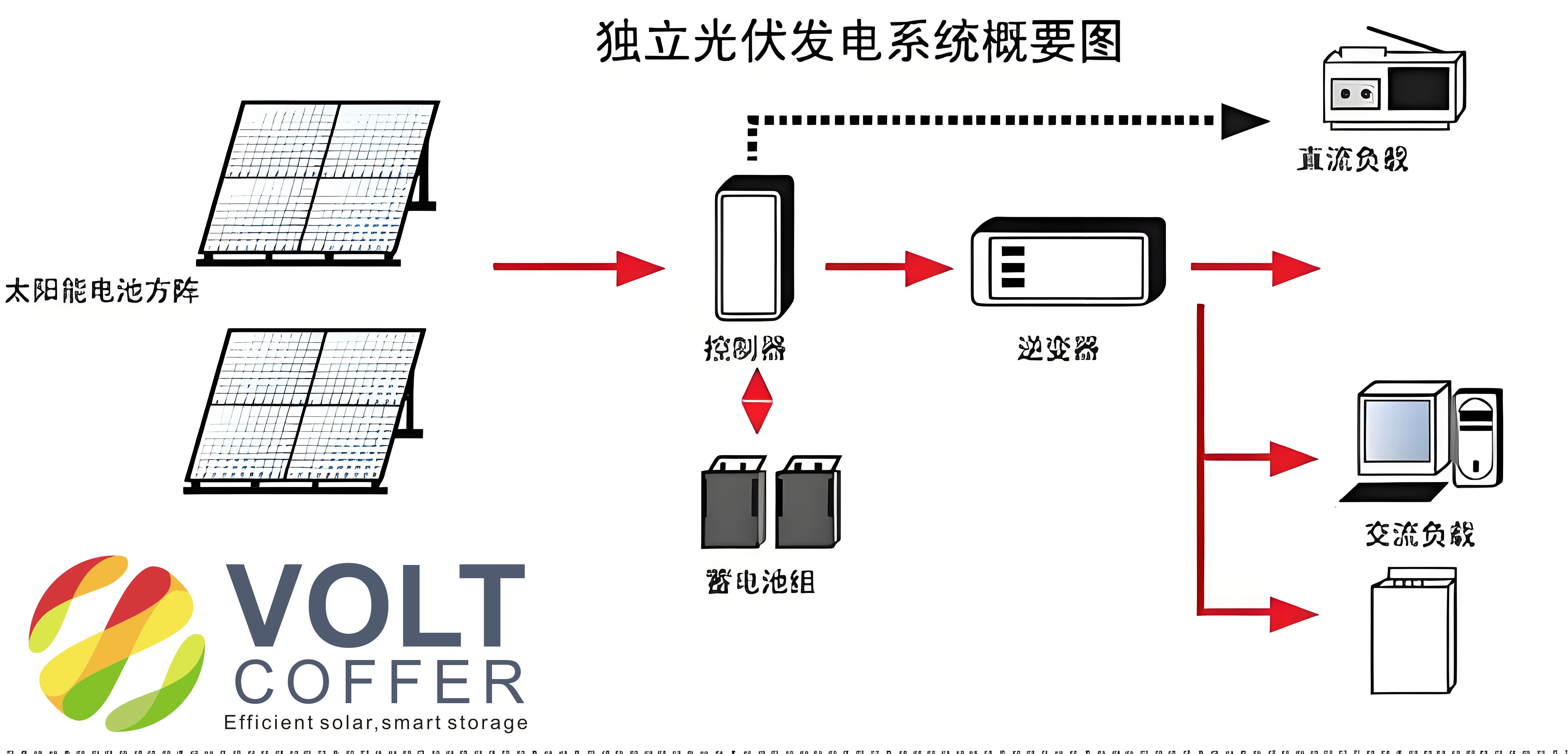
The typical structure of an off-grid solar system with VRFB storage includes PV arrays, a boost converter for MPPT, a DC-AC inverter for AC loads, and a bidirectional DC-DC converter for energy exchange with the battery. The PV arrays convert solar energy into DC electricity, which is then processed through the boost circuit to achieve maximum power tracking. Part of this power is inverted to AC for loads, while the remainder charges the VRFB via the bidirectional converter. During discharge, the VRFB supplies power back to the system, ensuring continuous energy availability. This configuration highlights the importance of coordinated control between the MPPT and charge-discharge mechanisms to optimize the overall performance of off-grid solar systems.
To model the PV array, we employ an equivalent circuit that accounts for the effects of temperature and irradiance. The output characteristics of a solar cell can be represented using the C1C2 model, which simplifies the complex physical relationships into practical equations. The current-voltage (I-V) and power-voltage (P-V) curves are derived as follows:
$$I = I_{sc} \left\{ 1 – C_1 \left[ \exp\left( \frac{V}{C_2 V_{oc}} \right) – 1 \right] \right\}$$
where the parameters \(C_1\) and \(C_2\) are defined as:
$$C_1 = \left(1 – \frac{I_m}{I_{sc}}\right) \exp\left(-\frac{V_m}{C_2 V_{oc}}\right)$$
$$C_2 = \left(\frac{V_m}{V_{oc}} – 1\right) \left[\ln\left(1 – \frac{I_m}{I_{sc}}\right)\right]^{-1}$$
Here, \(I_{sc}\) is the short-circuit current, \(V_{oc}\) is the open-circuit voltage, \(I_m\) is the current at maximum power, and \(V_m\) is the voltage at maximum power. These parameters vary with irradiance \(S\) and temperature \(T\), and can be adjusted using compensation coefficients:
$$I_{sc} = I_{scref} \frac{S}{S_{ref}} (1 + a \Delta T)$$
$$V_{oc} = V_{ocref} \ln(e + b \Delta S) (1 – c \Delta T)$$
$$I_m = I_{mref} \frac{S}{S_{ref}} (1 + a \Delta T)$$
$$V_m = V_{mref} \ln(e + b \Delta S) (1 – c \Delta T)$$
where \(S_{ref} = 1000 \, \text{W/m}^2\), \(T_{ref} = 25^\circ \text{C}\), \(\Delta T = T – T_{ref}\), \(\Delta S = S – S_{ref}\), and the compensation coefficients are typically \(a = 0.0025 \, ^\circ\text{C}^{-1}\), \(b = 0.0005 \, (\text{W/m}^2)^{-1}\), and \(c = 0.00288 \, ^\circ\text{C}^{-1}\). This model allows for accurate prediction of PV array behavior under diverse conditions, which is essential for designing effective control strategies in off-grid solar systems.
The MPPT algorithm is crucial for maximizing energy harvest from PV arrays. Traditional P&O methods use fixed step sizes, leading to oscillations around the maximum power point (MPP) and slow response times. To overcome these limitations, we propose a variable-step P&O MPPT algorithm that dynamically adjusts the perturbation step based on the power gradient. The voltage reference is updated as:
$$V_{ref} = V_{ref} + \alpha \frac{dP}{dV} = V_{ref} + \alpha \frac{P_k – P_{k-1}}{V_k – V_{k-1}}$$
where \(\alpha\) is a variable step-size factor that controls the tracking speed. When the power difference is large, the step size increases for faster convergence; when near the MPP, it decreases to minimize oscillations. This approach ensures rapid and accurate tracking, even under sudden changes in irradiance or temperature, which are common in off-grid solar systems. The algorithm operates in a cyclic manner, continuously monitoring and adjusting to maintain optimal performance.
To validate the MPPT strategy, we simulate the PV array and control algorithm using the parameters of a 250 W solar panel. The key specifications are summarized in Table 1.
| Parameter | Value |
|---|---|
| Open-Circuit Voltage (\(V_{oc}\)) | 36 V |
| Short-Circuit Current (\(I_{sc}\)) | 8.65 A |
| Maximum Power Voltage (\(V_m\)) | 30.4 V |
| Maximum Power Current (\(I_m\)) | 8.22 A |
| Maximum Power | 250 W |
| Conversion Efficiency | 17.6% |
Simulation results under different environmental scenarios demonstrate the effectiveness of the variable-step MPPT. For instance, under fixed temperature and irradiance, the algorithm converges to the MPP within 0.1 seconds with minimal oscillation. When irradiance changes abruptly, the system quickly adapts, maintaining high tracking accuracy. Similarly, temperature variations cause minor shifts in the MPP, but the algorithm compensates effectively, ensuring consistent performance in off-grid solar systems.
For charge-discharge control of VRFBs, we propose a SOC-based three-loop flexible strategy using a bidirectional DC-DC converter. The outer loop monitors the SOC to determine the operating mode (charge or discharge), the middle loop regulates voltage for constant-voltage charging, and the inner loop controls current for constant-current charging. All loops employ limited PID controllers to prevent overcharging or over-discharging, enhancing the safety and longevity of the battery. The bidirectional converter topology combines boost and buck circuits, allowing efficient energy flow in both directions. During charging, the buck circuit operates with the duty cycle \(\alpha\) relating the battery voltage \(U_s\) to the DC bus voltage \(U_{dc}\):
$$U_s = \alpha U_{dc}$$
During discharging, the boost circuit takes over, with the duty cycle \(\beta\) satisfying:
$$U_{dc} = \frac{1}{\beta} U_s$$
This configuration ensures seamless transitions between charge and discharge modes, which is critical for the reliability of off-grid solar systems. The three-loop control strategy is implemented as follows: the SOC loop compares the actual SOC with a reference value to initiate charging or discharging. If the SOC is below the reference, charging begins with the voltage loop saturated, setting a fixed current for constant-current charging. As the battery voltage rises, the system switches to constant-voltage charging, gradually reducing the current until the SOC reaches the desired level. For discharging, the process is reversed, with the SOC loop ensuring balanced energy flow.
Simulation of a 5 kW / 30 kWh off-grid solar system validates the charge-discharge control. Under varying irradiance and load conditions, the system maintains stable DC bus voltage and efficient battery operation. For example, when irradiance increases, excess power charges the VRFB, indicated by negative current flow; when load demand exceeds PV generation, the battery discharges, supplying positive current. The three-loop controller ensures smooth transitions between states, with voltage fluctuations quickly damped. This robustness is essential for off-grid solar systems, where energy availability must match demand without grid support.
In summary, the integration of advanced MPPT and charge-discharge control strategies significantly enhances the performance of off-grid solar systems. The variable-step P&O MPPT algorithm provides fast and accurate power tracking, while the SOC-based three-loop control ensures safe and efficient battery management. These contributions address key challenges in renewable energy integration, promoting the adoption of off-grid solar systems for sustainable power generation. Future work could explore real-time optimization and hardware implementation to further improve scalability and cost-effectiveness.
The development of off-grid solar systems relies heavily on innovative control techniques to handle the dynamic nature of solar energy. By combining adaptive MPPT with intelligent battery management, we can achieve higher efficiency, longer lifespan, and greater reliability. This approach not only benefits remote applications but also contributes to global efforts in reducing carbon emissions and fostering energy independence. As technology advances, off-grid solar systems will play an increasingly vital role in the transition to a clean energy future.
To further illustrate the system performance, Table 2 compares the key metrics of the proposed strategies under different operating conditions.
| Condition | MPPT Response Time | Charge-Discharge Efficiency | Voltage Stability |
|---|---|---|---|
| Fixed Irradiance and Temperature | < 0.1 s | > 95% | High |
| Sudden Irradiance Change | < 0.2 s | > 92% | Moderate |
| Temperature Variation | < 0.15 s | > 93% | High |
| Combined Changes | < 0.25 s | > 90% | Moderate |
Mathematical analysis of the system dynamics involves differential equations describing the power flow. For instance, the power balance in an off-grid solar system can be expressed as:
$$P_{pv} = P_{load} + P_{charge} – P_{discharge}$$
where \(P_{pv}\) is the PV output power, \(P_{load}\) is the load power, and \(P_{charge}\) and \(P_{discharge}\) are the battery powers. The SOC dynamics are governed by:
$$\frac{dSOC}{dt} = \frac{I_{bat}}{Q_{bat}}$$
where \(I_{bat}\) is the battery current and \(Q_{bat}\) is the battery capacity. These equations help in designing controllers that maintain energy equilibrium in off-grid solar systems.
In conclusion, the proposed control strategies offer a comprehensive solution for optimizing off-grid solar systems. Through detailed modeling, simulation, and analysis, we demonstrate their ability to enhance energy harvest, storage, and utilization. As the demand for decentralized power grows, such advancements will be instrumental in building resilient and sustainable energy infrastructures worldwide.