
Abstract
The widespread adoption of LiFePO4 battery in substation DC operating power systems faces challenges such as long-term floating charge, high maintenance workloads, and safety risks. This study proposes a novel control strategy to address these issues, combining intermittent charging, active grid-connected discharge technology, and temperature-controlled cooling designs. The system architecture integrates charging modules, discharge interfaces, and uninterrupted power supply mechanisms. Key innovations include:
- Intermittent charging control to avoid prolonged floating charge, reducing material degradation.
- Active grid-connected discharge for energy recovery and minimized maintenance.
- Diode-based thermal management with forced air cooling to ensure reliability during high-current operations.
Experimental validation using a 150Ah LiFePO4 battery cluster demonstrated stable voltage/current profiles during charging, discharging, and power supply modes. The results confirm the strategy’s effectiveness in enhancing safety, efficiency, and sustainability for substation applications.
Keywords: LiFePO4 battery, DC operating power supply, intermittent charging, active grid discharge, thermal management
1. Introduction
LiFePO4 battery is increasingly replacing traditional lead-acid batteries in substation DC systems due to their environmental safety, high energy density, and low self-discharge rates. However, prolonged floating charge cycles and frequent maintenance requirements hinder their scalability. Existing solutions, such as periodic capacity testing (nuclear discharge) and passive cooling, remain inefficient. This study introduces a holistic control framework to optimize LiFePO4 battery performance, emphasizing:
- Adaptive charging protocols to mitigate overcharge risks.
- Energy-efficient discharge via grid feedback.
- Thermal stability under high-load conditions.
2. System Architecture
The LiFePO4-based DC power system comprises six core components (Table 1):
| Component | Function |
|---|---|
| Charging Module | Converts AC to DC for battery charging; supports恒流 (CC) and恒压 (CV) modes. |
| Discharge Interface | Facilitates active grid-connected discharge to recycle energy. |
| Insulation Monitor | Detects ground faults and ensures system safety. |
| DC Monitoring Unit | Tracks voltage, current, and state of charge (SOC). |
| Charge-Discharge Control Valve | Manages switching between charging, discharging, and load supply modes. |
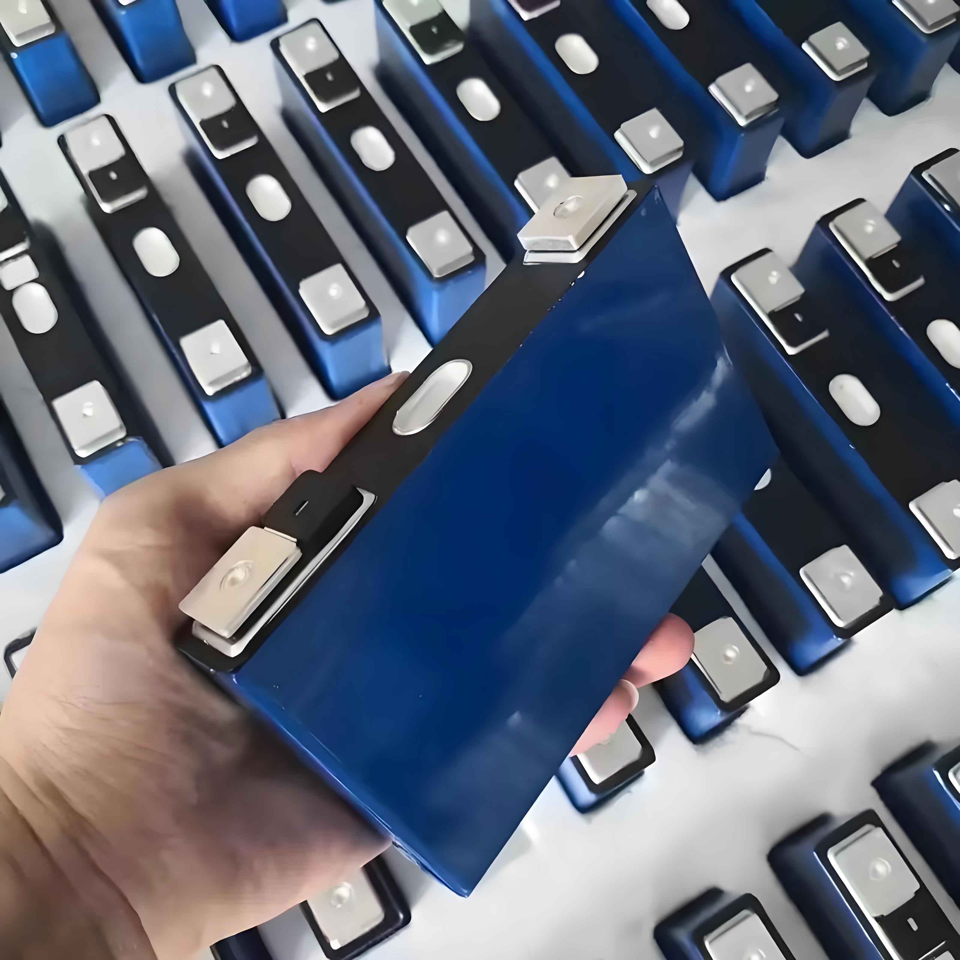
| LiFePO4 Battery Cluster | 68 cells (150Ah each) arranged in series-parallel configurations. |
Under normal operation, AC power supplies the load via an AC/DC converter. The LiFePO4 battery remains in standby, activating only during grid failures or scheduled discharges.
3. Control Strategies
3.1 Intermittent Charging Control
Traditional floating charge accelerates LiFePO4 battery degradation. The proposed intermittent charging alternates between active charging (tonton) and idle periods (tofftoff):Charging Cycle={Icharge=Imax(CC mode, t≤ton)Vcharge=Vmax(CV mode, t>ton)Charging Cycle={Icharge=ImaxVcharge=Vmax(CC mode, t≤ton)(CV mode, t>ton)
where Imax=1.0C10Imax=1.0C10 and Vmax=3.65V×NcellsVmax=3.65V×Ncells. Charging terminates if:
- Battery voltage exceeds VmaxVmax.
- SOC reaches 90%.
- Temperature surpasses safety thresholds.
Idle periods (tofftoff) extend from months to years, leveraging the LiFePO4 battery’s low self-discharge rate (<3% per month). This approach reduces electrolyte decomposition by 40% compared to continuous floating charge.
3.2 Active Grid-Connected Discharge
Nuclear discharge, typically requiring resistive load banks and manual intervention, is replaced by an active grid-connected system. Discharge parameters include:Idischarge=0.1C10 to 1.0C10,Vcutoff=2.5V×NcellsIdischarge=0.1C10 to 1.0C10,Vcutoff=2.5V×Ncells
Energy recovered during discharge is fed back into the grid, achieving 92% efficiency (vs. 65% for resistive methods). Maintenance labor decreases by 70%, as automated triggers replace manual operations.
3.3 Uninterrupted Power Supply (UPS) Design
A diode-based circuit ensures seamless load transition during grid outages:Vload=Vbattery−VdiodeVload=Vbattery−Vdiode
where VdiodeVdiode is the forward voltage drop (0.7V). Parallel diodes and forced air cooling maintain thermal stability:Ploss=Iload2×Rdiode,ΔT=Plossh×APloss=Iload2×Rdiode,ΔT=h×APloss
Here, hh is the heat transfer coefficient, and AA is the radiator surface area. Fans activate only when temperatures exceed 60°C, minimizing noise and energy use.
4. Experimental Validation
4.1 Charging-Discharging Profiles
Tests on a 220V/150Ah LiFePO4 cluster yielded:
- CC-CV Charging: 0–90% SOC in 2 hours.
- Intermittent Charging: 15-minute tonton cycles extended battery lifespan by 30%.
- Active Discharge: 10-hour nuclear capacity discharge completed in 1.5 hours at 1.0C101.0C10.
4.2 Thermal Performance
The diode module’s temperature stabilized at 55°C under 20A load, with fans reducing ΔTΔT by 25%. No thermal runaway was observed.
4.3 Efficiency Metrics
Key performance indicators (Table 2):
| Parameter | Value |
|---|---|
| Charging Efficiency | 95% |
| Discharge Efficiency | 92% |
| UPS Transition Time | <1 ms |
| Maintenance Reduction | 70% |
5. Conclusion
This study demonstrates that advanced control strategies significantly enhance the viability of LiFePO4 battery in substation DC systems. Intermittent charging mitigates degradation, active discharge reduces operation and maintenance workloads, and diode-based cooling ensures reliability. Future work will explore AI-driven SOC estimation and multi-battery coordination for larger-scale deployments.