
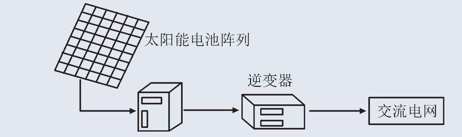
Photovoltaic power generation is an important direction of new energy research, and photovoltaic grid connected inverters are an important part of photovoltaic power generation systems. The structure of photovoltaic power generation systems is usually composed of two parts, namely the photovoltaic array and the grid connection part, as shown in Figure 1.
In Figure 1, the frequent start and stop of switching devices in the photovoltaic inverter during operation can cause a certain amount of harmonics on its output side. When photovoltaic power generation energy is transmitted through wires, the equivalent impedance of the wires and the stray inductance and capacitance of the system may amplify these harmonics. In order to improve the output effect of the system, L-type, LC type, and LCL type filters are commonly used to eliminate harmonics in photovoltaic power generation systems.
Based on the analysis of common filter structures and characteristics, LC and LCL filters can suppress harmonics higher than the resonant frequency, and have fast attenuation response speed, making them widely applicable in the design of photovoltaic grid connected inverters. LCL type filters have better decoupling ability compared to LC type filters compared to the grid impedance, but it is necessary to consider the resonance peak at the resonance frequency and the current ripple generated at the inductance, which can have adverse effects on the grid during grid connection.
Resonance is an important direction in the research of photovoltaic grid connected inverters. According to the causes of resonance, damping control can be added to the system of photovoltaic grid connected inverters to suppress resonance at the resonant frequency. There are mainly two types of damping control in photovoltaic grid connected inverters: passive damping and active damping. Passive damping is the simplest and most direct control method, and is not limited by the frequency of the switching devices used. However, this method mainly utilizes resistors connected in series or parallel across various branches of the filter to increase system damping, increase additional power consumption, and thus reduce system efficiency. Active damping mainly utilizes intelligent control algorithms to overcome the disadvantages of passivity, without the need for additional electrical components in the filter and without additional power consumption. In order to achieve active damping control, a method based on capacitor current feedback control was proposed to achieve damping, and a damping method using capacitor voltage feedback was proposed. However, these methods require the addition of sensors, which increases the complexity and cost of control. Later, research proposed the use of split capacitor method to convert a third-order system into a first-order system to solve the resonance problem, but it is difficult to achieve in practical engineering. The commonly used controllers in linear control of power grid current include proportional integral (PI) controllers, proportional resonance (PR) controllers, and predictive control. However, these controls have drawbacks such as complexity and poor grid connected dynamic performance. It is also necessary to suppress resonance caused by current harmonics on the inverter side and voltage harmonics on the grid side near the resonance frequency.
This article establishes a Hamiltonian system (PCHD) mathematical model based on the structure and working principle of the LCL type photovoltaic grid connected inverter, applies a passive controller to control the system, and finally verifies the effectiveness of the proposed method through simulation.
1. Mathematical model of three-phase LCL photovoltaic grid connected inverter
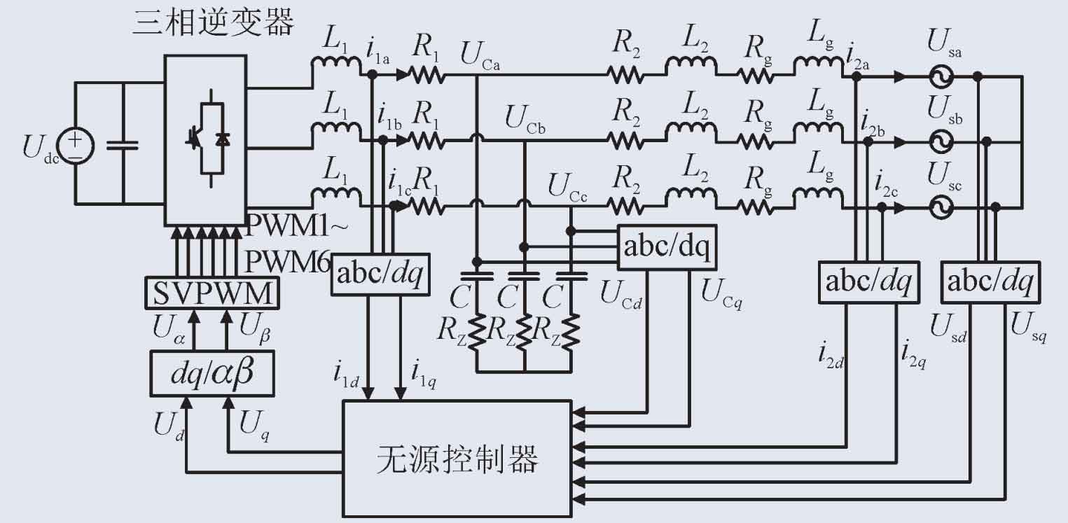
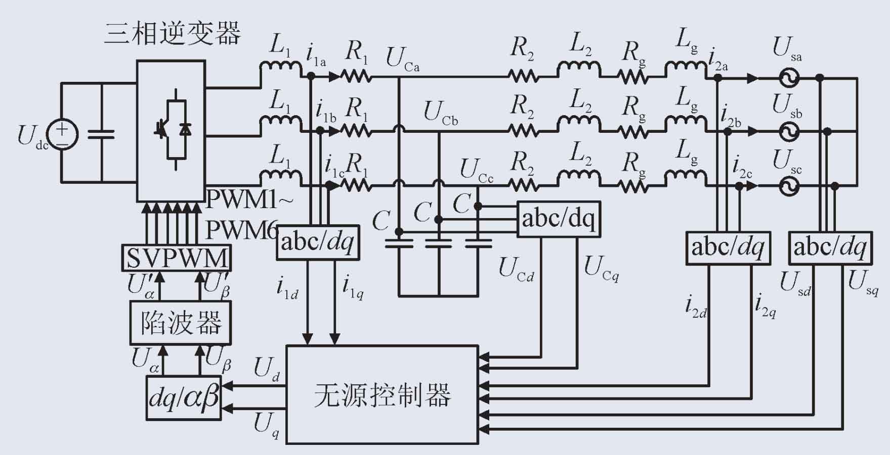
The topology structure of the three-phase LCL photovoltaic grid connected inverter is shown in Figure 2.
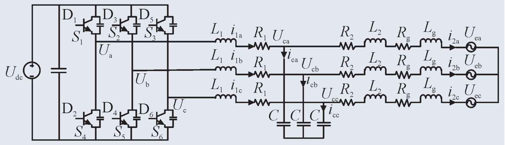
In the topology structure of Figure 2, Udc is the DC side voltage source for grid connection of the photovoltaic inverter; D1~D6 are the six IGBT switches on the bridge of the photovoltaic inverter; S1~S6 are the driving signals of each bridge arm of the photovoltaic inverter; Inductance on L1 inverter side; L2 is the inductance on the grid side; R1 and R2 are the resistances on the inverter side and grid side, respectively, and are the equivalent resistances generated by the output of the photovoltaic inverter.
The expression of the three-phase LCL photovoltaic grid connected inverter in the dq axis can be obtained by using KVL and KCL:
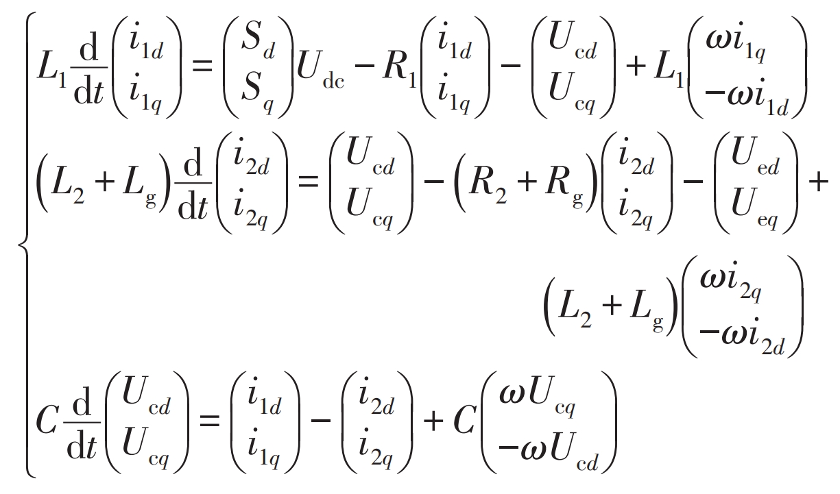
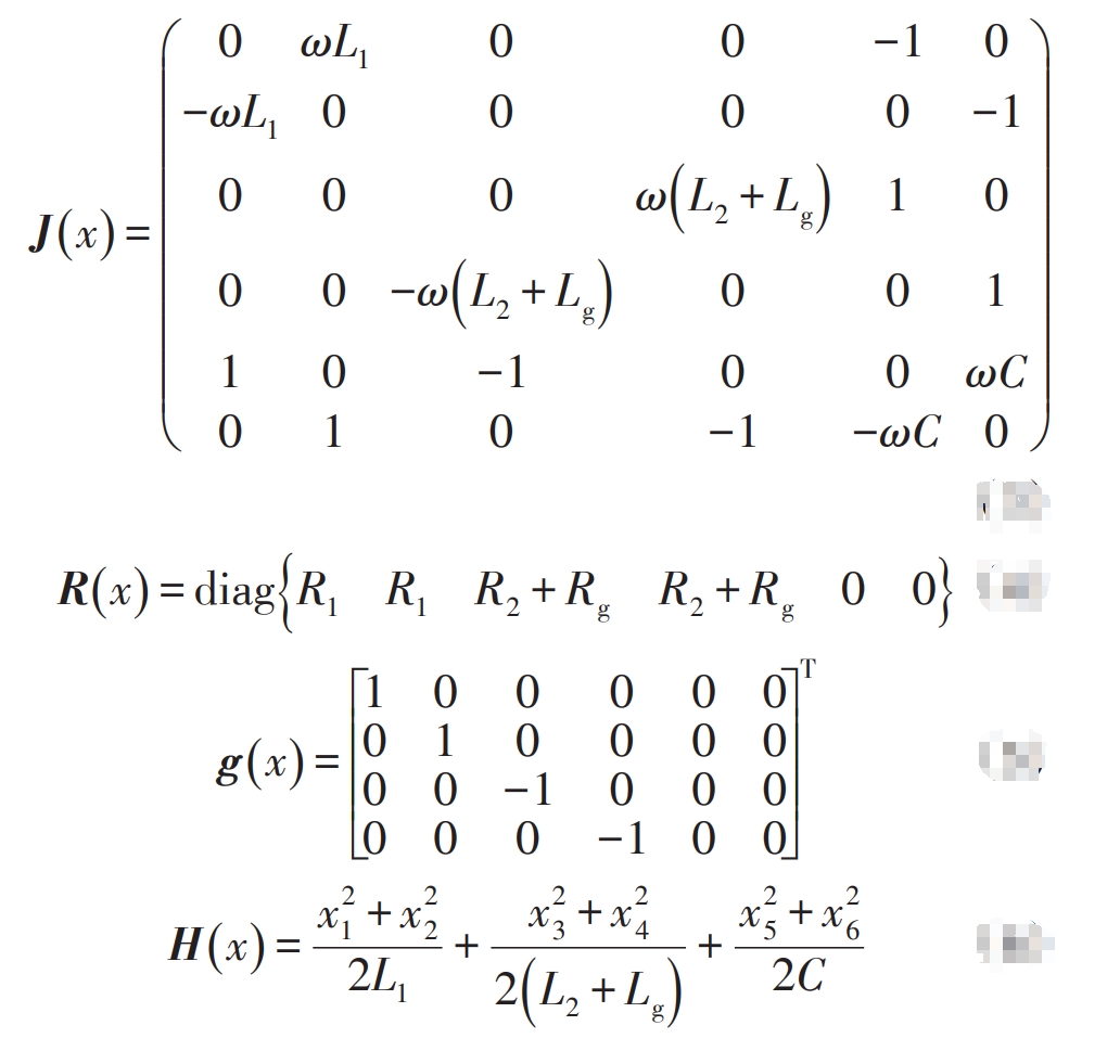
In the formula, Sd and Sq represent the components decomposed by the switching function on the d-axis and q-axis. By using the Hamiltonian function to transform the formula, we can obtain:
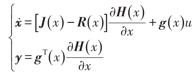
In the formula, J (x) is the internal structure matrix of the system; R (x) is the system dissipation matrix; G (x) is the internal and external interconnection matrix of the system, indicating the internal and external interconnection situation of the system; H (x) is the Hamiltonian function of the system, reflecting the energy in the energy storage components of the system.
2. Design of passive controller for LCL type photovoltaic grid connected inverter
2.1 System Passivity Analysis
Hamilton theory is widely used in the analysis of modeling and control methods for electrical and mechanical systems. A grid connected inverter system model can be established based on Hamilton theory, and the system output is:
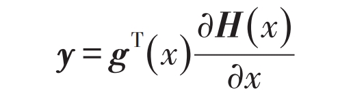
The dissipative inequality of the system can be obtained as:
According to the dissipative inequality, there is a law of energy change in the inverter system, that is, the growth rate of energy is always smaller than the energy injection supply rate outside the inverter system. This indicates that the LCL grid connected inverter system is a passive system, allowing for research and design of passive controllers.
2.2 Controller Design
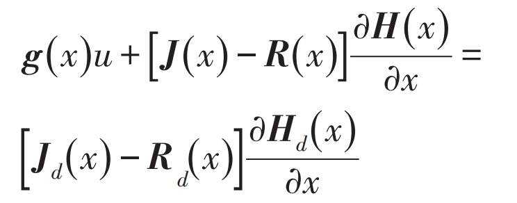
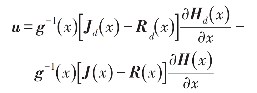
The design concept of passive control for harmonic damping is to first determine a control rate such that the closed-loop PCHD model of the system is:
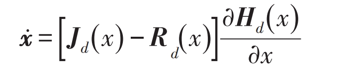
In the formula, there exists J (dx)=J (a x)+J (x), R (d x)=R (a x)+R (x), H (d x)=H (a x)+H (x), where a vector K (x)=partial H (a x)/partial x is introduced, and K (x) satisfies integrability:
At the equilibrium point, there are:
Lyapunov stability is:
Make:
In the formula, R (d x)=R (d x) T. The passive control rate of the obtained system is:
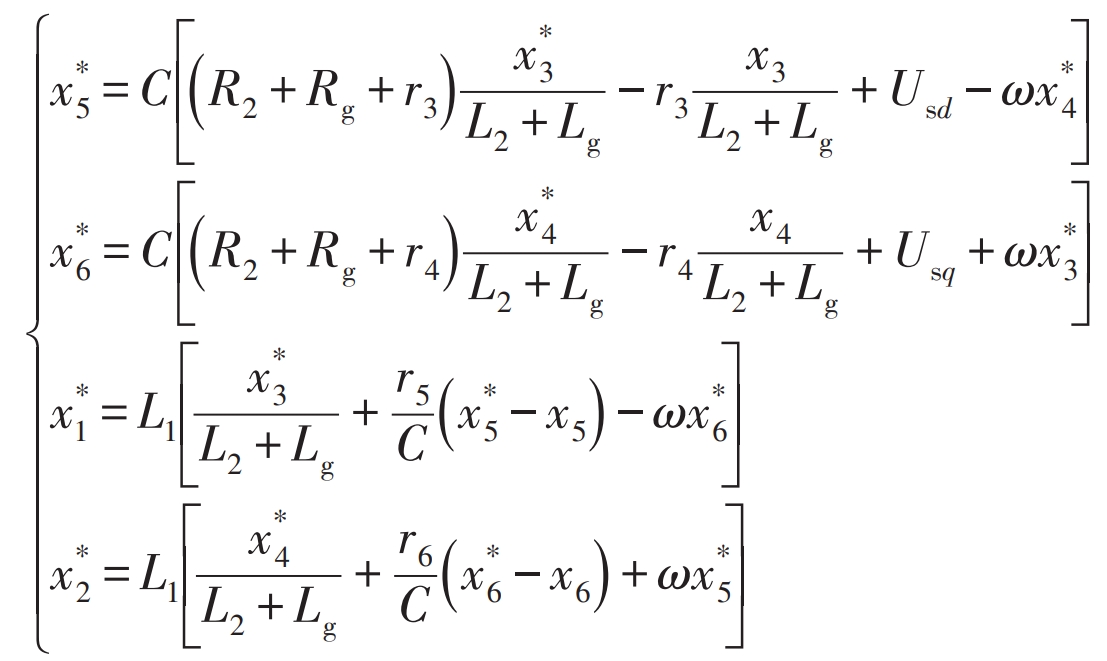
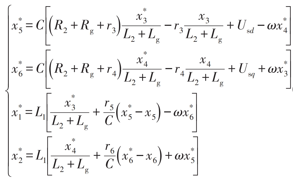
According to the formula, control and design the photovoltaic inverter, taking J (a x)=0, R (a x)=diag {r1 r2 r3 r4 r5 r6}. Select the grid side current as the control object, making x3 → x3 *, x4 → x4 *, and calculate the asymptotic tracking reference values of x1, x2, x5, and x6 with x3 and x4 through mathematical model equations, ultimately achieving x → x *.
Obtain the reference value of the system state variable:
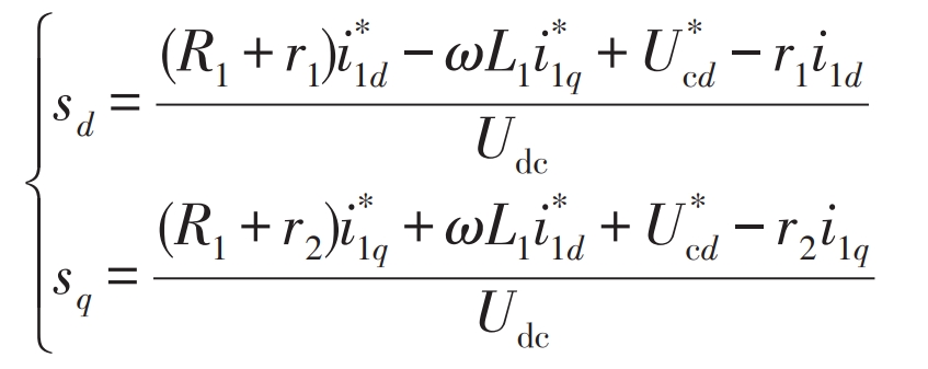
In order to obtain the control law of the system, the formula can be combined with the system control equation to obtain the components on two coordinate axes, that is, the system control rate is:
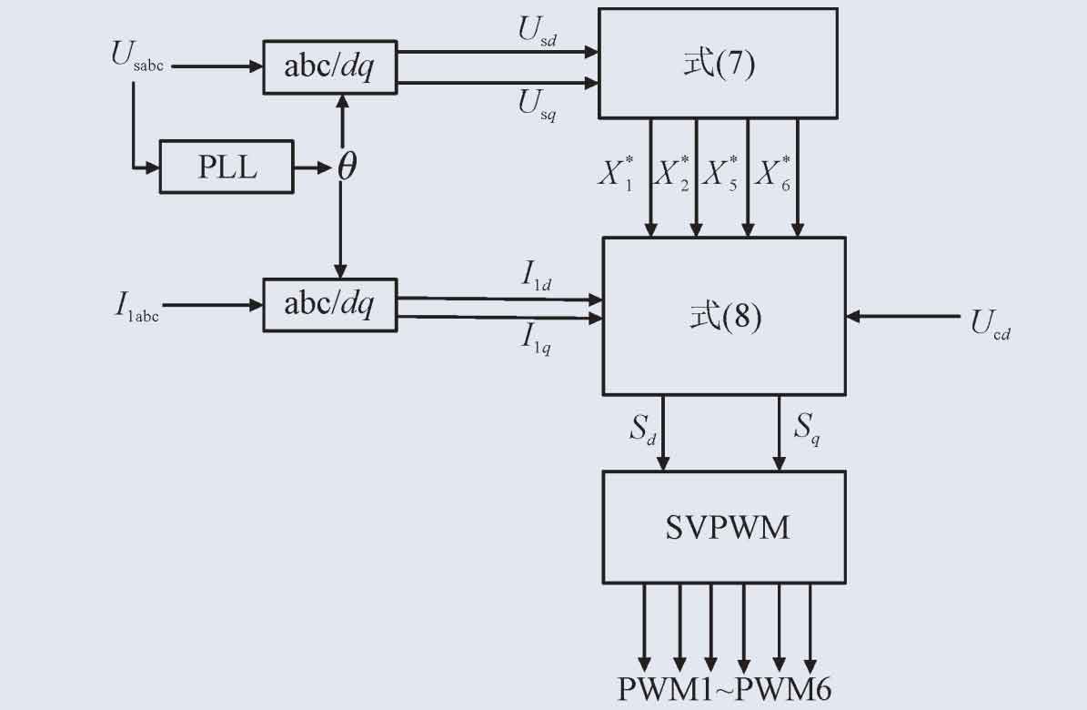
In summary, the passive controller diagram of the three-phase LCL photovoltaic grid connected inverter under the weak current grid is shown in Figure 3.
According to the analysis and research on the control methods of photovoltaic inverters, in order to enhance the damping of the inverter system, the inverter system designed on the basis of a passive controller is shown in Figure 4.

2.3 Damping suppression optimization
Analysis of the LCL type photovoltaic grid connected inverter shows that the resonance problem caused by the LCL type filter can cause system oscillation and have adverse effects on grid connection. In order to overcome the resonance problem, it is necessary to increase the damping of the system. The passive damping method only requires series or parallel resistors in the three branches of the LCL filter. The expected balance formula of the system after combining the passive damping method of series damping resistance of filtering capacitor branches with the passive controller is shown in the formula.
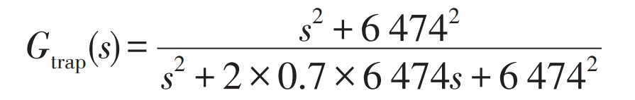
The method of adding damping resistance in photovoltaic grid connected inverters is only applicable to the low frequency range and increases system losses. In order to avoid adding electrical components while also suppressing high-frequency bands, this article chooses a notch filter to suppress harmonics. The transfer function of the notch filter used is:
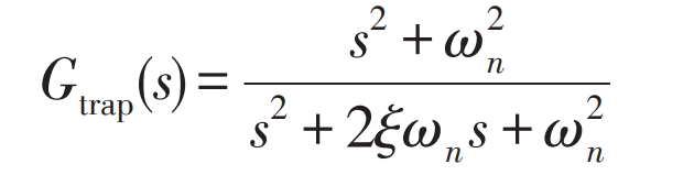
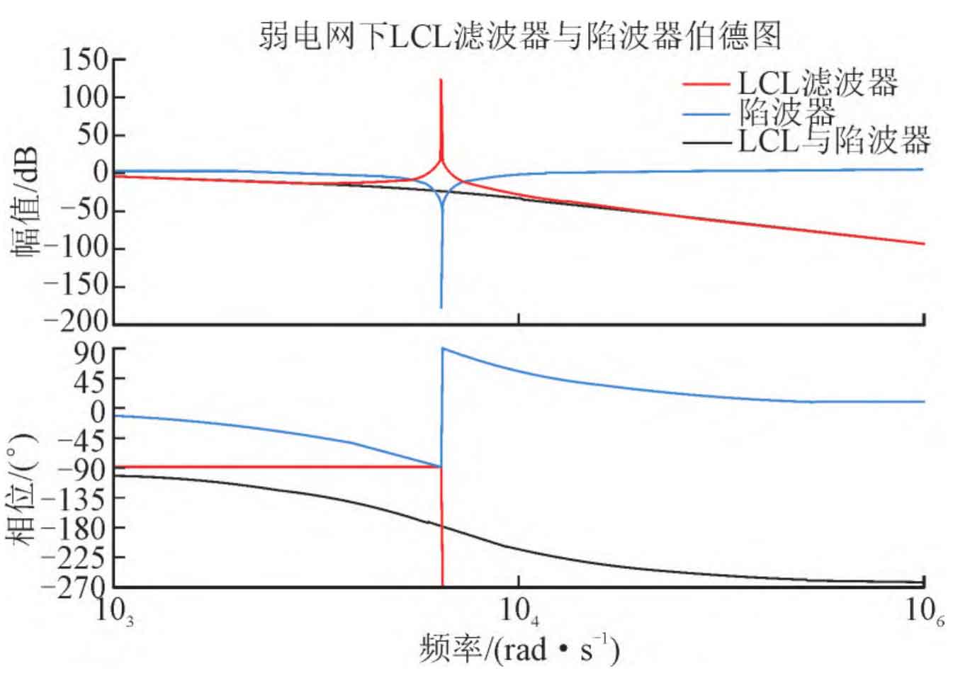
In the formula, x is the damping coefficient of the notch filter; Wn is the reverse resonant angular frequency of the notch filter. The Bode plot of the notch filter can be obtained through the transfer function of the notch filter, as shown in Figure 5.
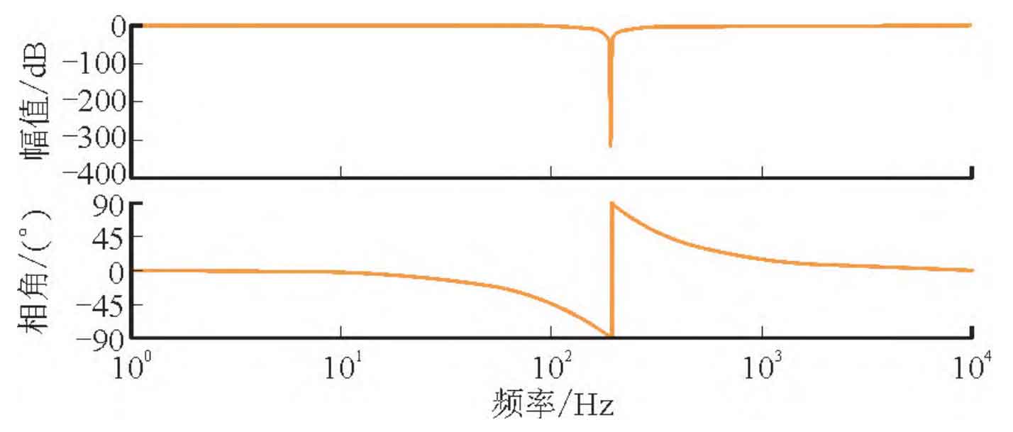
According to the transfer function of the notch filter in the formula, it is known that a large reverse gain will be generated at the frequency wn, and the gain at other corresponding frequencies is 0. Therefore, after adding a notch filter, the reverse spike of the notch filter can cancel out the forward spike at the system frequency, achieving the effect of suppressing resonance spikes.
3. Simulation experimental research
According to the designed control method, series resistors are connected to the capacitor branch of the filter, and the overall control system is shown in Figure 6.
On the basis of a simple passive controller, based on passive control simulation and the research methods in this paper, a damping resistor RZ=1 W is connected in series on the capacitor branch. The inductance of the inverter side and grid side is L1=1.5 mH and L2=0.5 mH, respectively, according to the size of the designed photovoltaic inverter and the suppression of current ripple. The equivalent resistances of the grid side and grid side are R2=0.05 Ω and Rg=0.05 Ω, respectively, and the filtering capacitor C=50 mF, Grid resistance inductance Lg=2 mH.
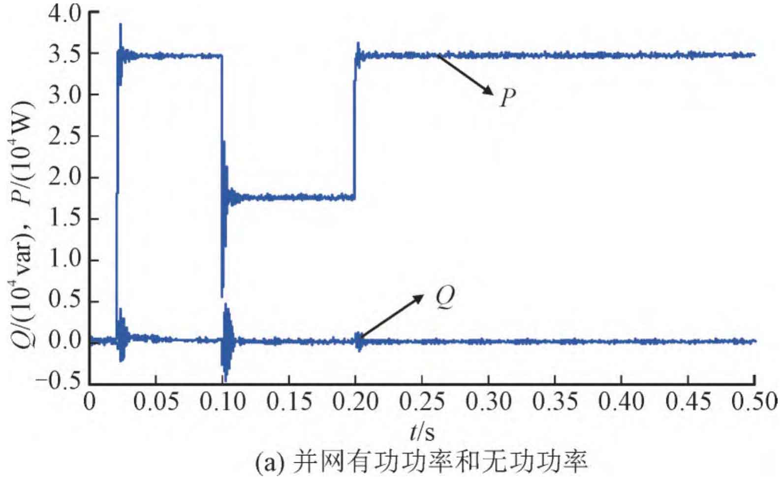
The system model shown in Figure 4 was established in MATLAB/SIMULINK, and the damping coefficients in the simulation models used were set as r1=100; R2=100; R3=r4=r5=r6=0.1. In order to simulate the dynamic response process of the system under sudden reduction conditions in practical engineering, the control active current i2d is directly increased to 90 A after startup, and then decreased by 45 A after 0.10 seconds. In order to simulate the sudden increase in operating conditions of the system, the control active current i2d is raised from 45 A to 90 A at startup after 0.1 seconds. The main purpose of doing so is to facilitate the observation of the entire dynamic response process. The simulation waveform is shown in Figure 7.
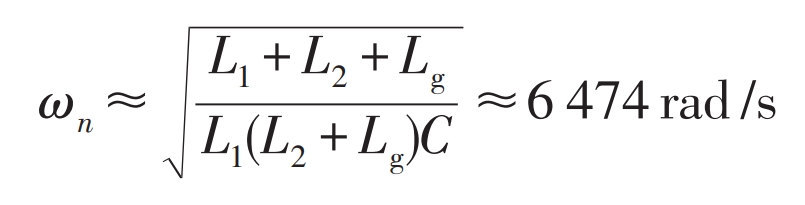
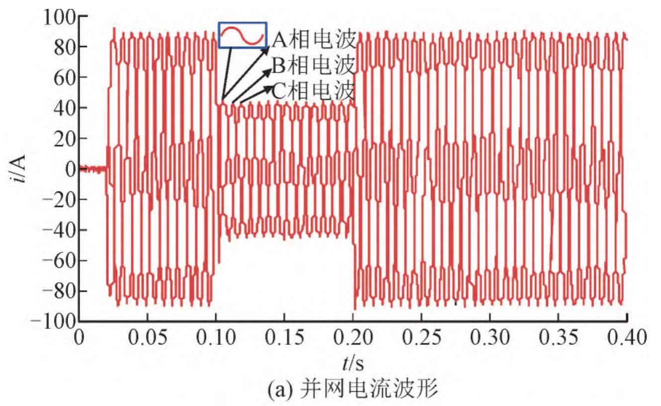
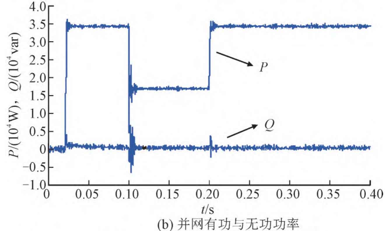
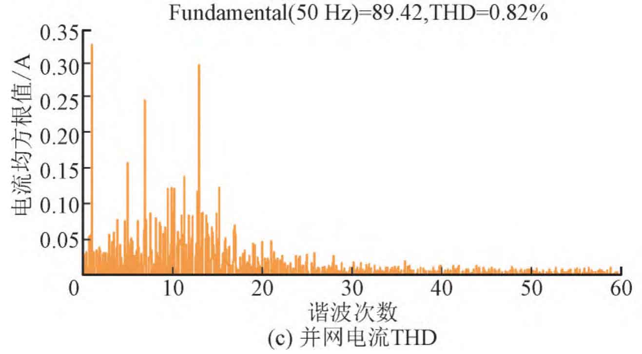
Figure 7 (a) shows the waveform of the grid connected current. It can be seen from the figure that the current error and speed of the passive control system with the addition of passive damping method are very good. As shown in Figure 7 (b), the grid connected power factor of the system is shown, and it can be seen from the figure that the active power factor and reactive power factor are both high. As shown in Figure 7 (c), the total harmonic distortion (THD) of the grid connected current is displayed. The output fundamental frequency value of the grid connected current is 89.42 A, and the total THD is 0.82%. According to the parameters in the previous text, the reverse resonance angular frequency of the notch filter can be calculated ω N is:
order ω N= ω R=6 474 rad/s, x=0.7, and the transfer function of the notch filter is:
Using the notch filter active damping method, the passive controller needs to be transformed into the ab axis to achieve harmonic peak suppression at a specific frequency. The control block diagram of the system has been changed to Figure 9.
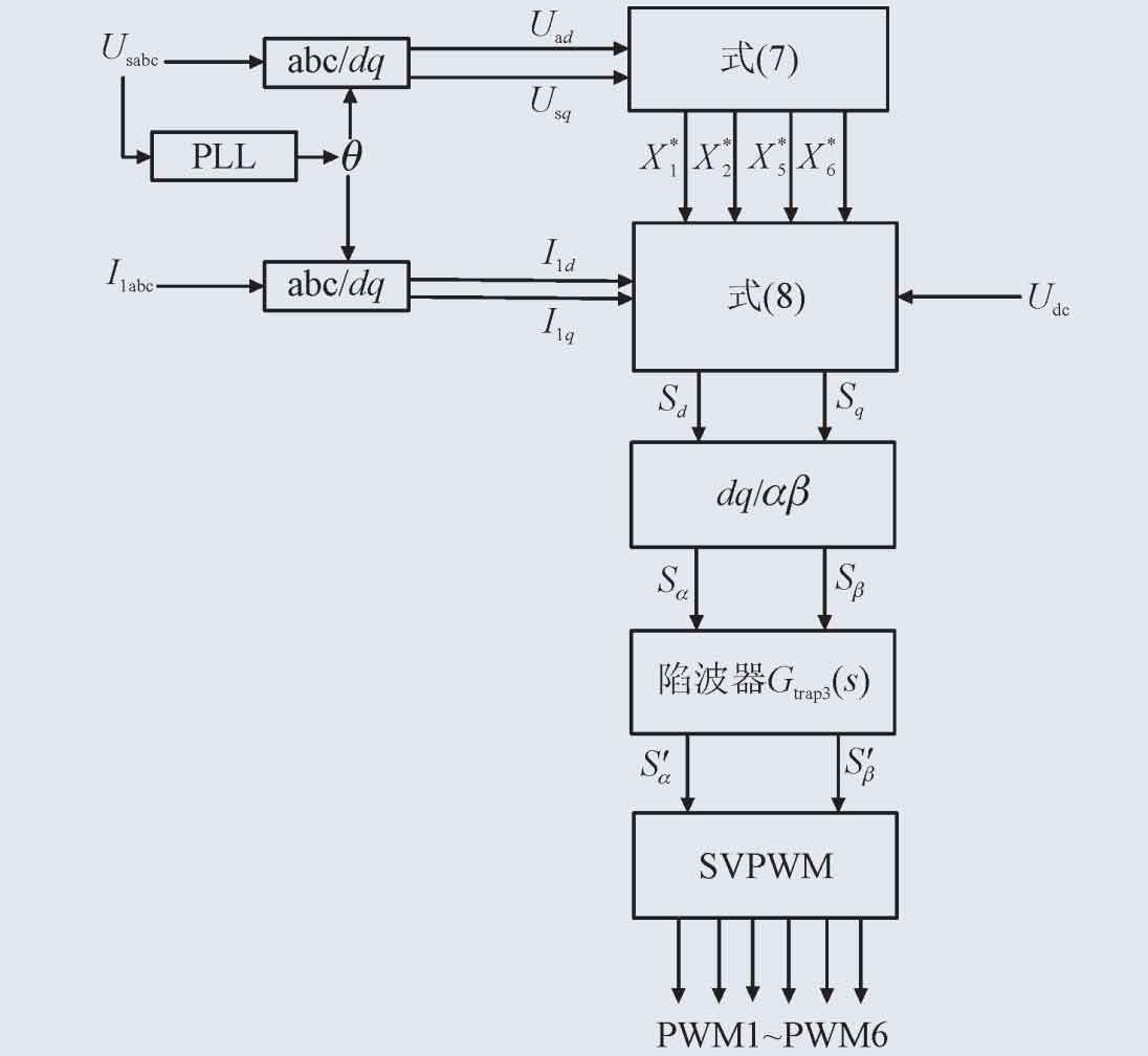
The structure of an active damping photovoltaic inverter based on a notch filter is shown in Figure 10.
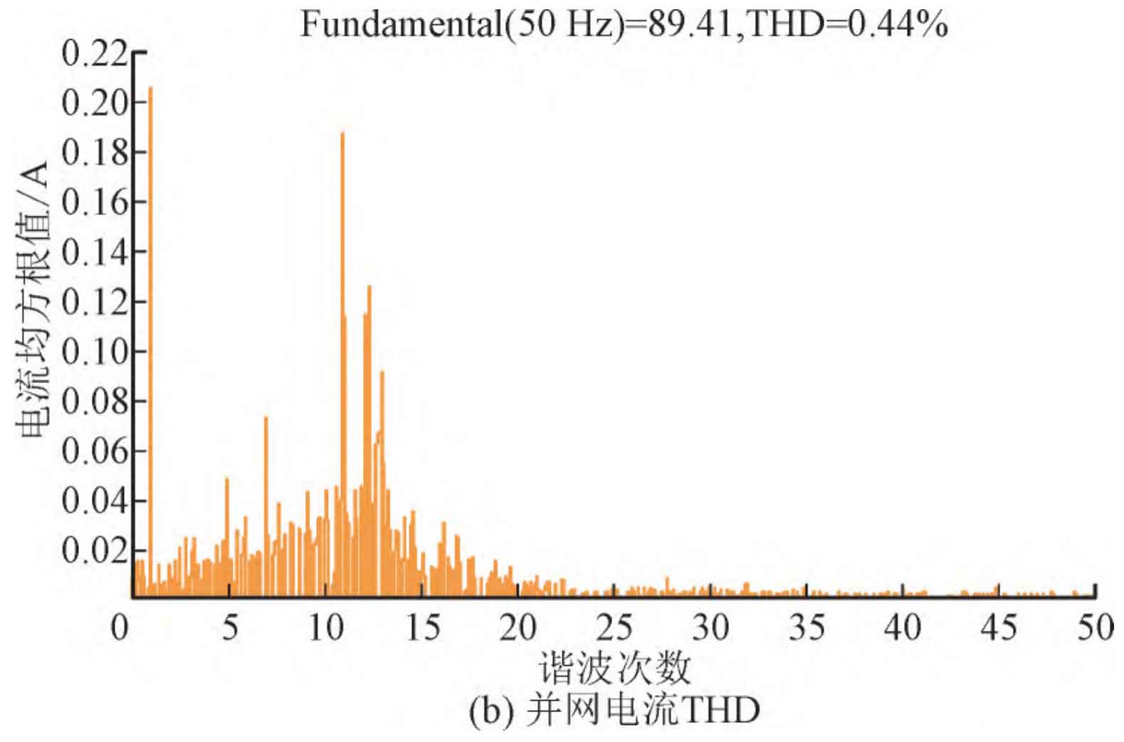
According to the structure of the active damping photovoltaic inverter with a notch filter in Figure 10, a simulation control model is built in MATLAB/SIMULINK, and the same parameters are set based on the simulation of a passive controller in a weak current network. The simulation results using the notch filter active damping control are shown in Figure 11. As shown in Figure 11 (a), the system power factor meets the requirements, and it has a high power factor both at rated load and at half load. As shown in Figure 11 (b), the system has a lower harmonic content in each frequency band, with a THD of 0.44%.
4. Conclusion
This article conducts in-depth research on the control of photovoltaic grid connected inverters in the context of the current grid connection of new energy generation. Based on the control requirements of photovoltaic grid connection, the quality and harmonic content of electrical parameters for grid connection are analyzed and studied. In order to meet the requirements of grid connected electrical quality in the power system, the LCL type photovoltaic grid connected inverter and PCHD system were analyzed, and a mathematical model was established. Based on the passive controller, an active damping control based on a notch filter was proposed to improve the output performance in the high frequency range. Simulation verified that the photovoltaic grid connected inverter can output stable waveforms under the proposed control method, The harmonic content meets the grid connection requirements. The next step will be to study the high-frequency oscillation of photovoltaic grid connected inverters, combining advanced intelligent control algorithms with active damping control to design a more intelligent and high-performance control strategy.