
In the operation of a battery energy storage system, maintaining state-of-charge (SoC) consistency across individual cells within a cluster is paramount. Inconsistencies lead to the “bucket effect,” where the cluster’s usable capacity is limited by the weakest cell, reducing overall energy throughput and accelerating the degradation of the overworked cells. To mitigate this, cell balancing is essential. While Battery Management Systems (BMS) offer automatic passive or active balancing, their effectiveness is often constrained by low balancing currents (typically <1A), thermal limitations, and limited balancing duration. For large-capacity battery energy storage systems, manual power replenishment—using external charging/discharging equipment—presents a superior alternative. This method offers higher currents (e.g., 2-10A), faster convergence, and is particularly crucial during system commissioning or after prolonged operation where significant inconsistencies develop. However, a lack of standardized methodology can lead to operational errors like incorrect, excessive, or insufficient replenishment. Based on extensive field experience, this article details a comprehensive framework for manual power replenishment, covering inconsistency diagnosis, cell selection, replenishment calculation, and operational procedures, all aimed at optimizing the performance and lifespan of the battery energy storage system.
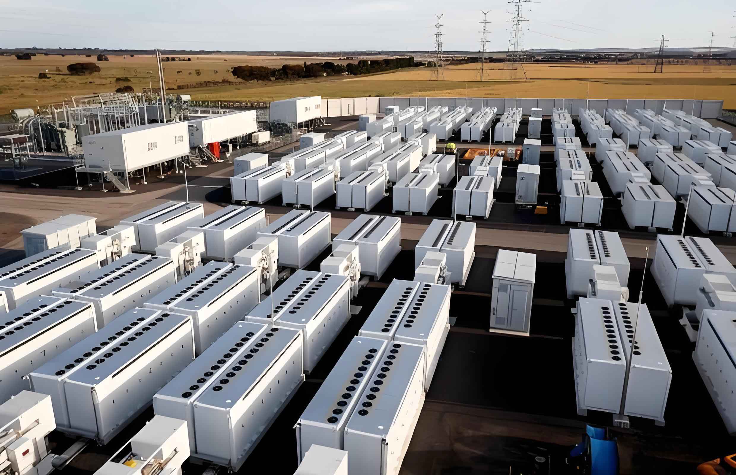
The foundational step in managing a battery energy storage system is accurately diagnosing when an imbalance necessitates manual intervention. Relying on a single metric can be misleading; therefore, a multi-criteria approach is recommended. The following table synthesizes key判据 from standards and practical engineering thresholds.
| Criteria Category | Specific Criterion | Threshold / Basis | Description |
|---|---|---|---|
| Dynamic Voltage | Voltage spread at end of charge | > 250 mV | Per GB/T 36276-2018 draft. Measured at termination of a full charge cycle. |
| Dynamic Voltage | Voltage spread at end of discharge | > 300 mV | Per GB/T 36276-2018 draft. Measured at termination of a full discharge cycle. |
| Static Voltage | Voltage spread after resting post-charge | > 20 mV | Engineering practice. Voltage measured after >3 hours rest following a full charge. |
| Static Voltage | Voltage spread after resting post-discharge | > 100 mV | Engineering practice. Voltage measured after >3 hours rest following a full discharge. |
| Energy Throughput | Actual charge energy of cluster | < N × Qcell × η | N: number of cells; Qcell: rated cell capacity (Ah); η: reliability factor (~0.9). Indicates underutilization. |
| Energy Throughput | Actual discharge energy of cluster | < N × Qcell × η | Same as above. A primary indicator of capacity limitation due to inconsistency. |
A robust composite判据 for initiating manual replenishment in a battery energy storage system can be defined as:
$$ \text{Replenishment Needed} = (C1 \lor C2 \lor C3 \lor C4) \land (C5 \lor C6) $$
Where C1 to C6 correspond to the criteria in the table above, \(\lor\) denotes the logical OR, and \(\land\) denotes the logical AND. This ensures action is taken only when both a voltage/energy anomaly is detected and it is impacting system performance.
Once an imbalance is confirmed, precisely identifying which cells require replenishment is critical. This is most accurately performed using voltage data from the extremes of the SoC range (high or low), where the voltage-SoC sensitivity is highest for LiFePO4 batteries. Assume we have voltage data \(U_i\) for each cell \(i\) in a cluster of \(N\) cells, typically measured at the end of a discharge (low SoC). Three complementary selection methods are presented below.
| Method | Principle & Formula | Threshold Setting | Pros & Cons |
|---|---|---|---|
| Threshold Comparison | Flags cells whose voltage deviates from the cluster mean by more than a set value. $$ |U_i – U_{avg}| > U_{set} $$ $$ U_{avg} = \frac{1}{N}\sum_{i=1}^{N} U_i $$ |
\(U_{set}\) is typically 150-250 mV for discharge data. | + Simple, intuitive. – Sensitive to the mean, which can be skewed by outliers. |
| Significance Criterion | Uses statistical outliers. Calculates mean and standard deviation after removing the global max and min to avoid skew. $$ \mu = \frac{\sum_{i=1}^{N} U_i – U_{max} – U_{min}}{N-2} $$ $$ \sigma = \text{StDev}(\{U_1, U_2, …, U_N\} \setminus \{U_{max}, U_{min}\}) $$ The significance metric is: $$ M(U_i) = \frac{U_i – \mu}{\sigma} $$ |
Cell \(i\) is flagged if \( |M(U_i)| > \theta \). Theoretically, \(\theta=3\), but \(\theta=6\) is used in practice to avoid false positives. | + Robust to a small number of severe outliers. – Slightly more complex calculation. |
| Scatter Plot Visualization | Plots all cell voltages in a cluster. Cells visually isolated from the main cluster are identified. | Visual inspection. | + Provides immediate, intuitive insight into the distribution and severity of imbalance. – Subjective; best used to corroborate numerical methods. |
In practice, these methods should be used conjunctively. For instance, applying all three to a dataset from a 416-cell battery energy storage system discharge yielded identical results: three specific cells (e.g., M06B19, M06B44, M06B49) were consistently flagged by all methods as having significantly lower voltage, confirming them as targets for charging replenishment.
With target cells identified, the next step is determining how much energy to add or remove. Two principal methods exist: Fixed Energy Replenishment and Cut-off Voltage Replenishment. The choice depends on data availability and operational convenience.
1. Fixed Energy Replenishment Method
This method calculates a precise ampere-hour (Ah) quantity to transfer. It has two variants:
a) OCV-SoC Calculation: This method requires the battery to be at rest (>3 hours) at a low or high SoC state. The Open Circuit Voltage (OCV) is measured for the target cell \(U_{ocv}\) and the average of normal cells \(U_{avg}\). Using the known OCV-SoC curve \(SoC(U)\), the replenishment energy is:
$$ Q_{dlt} = \frac{(SoC(U_{ocv}) – SoC(U_{avg})) \times Q_{norm}}{\eta} $$
Where \(Q_{norm}\) is the rated cell capacity (Ah), and \(\eta\) is the charge/discharge efficiency (\(\approx 0.995\) for charge, \(\approx 1.005\) for discharge). A positive \(Q_{dlt}\) indicates required discharge; negative indicates required charge.
b) Charge/Discharge Data Calculation: This requires BMS cycle data. Let \(Q_{abn}(t)\), \(U_{abn}(t)\) be the cumulative throughput and voltage of the abnormal cell, and \(Q_{wel}(t)\), \(U_{wel}(t)\) be those of a representative normal cell. At the cycle end time \(t_{end}\):
– If the target cell is at higher SoC (discharges last), find the time \(t_0\) when the normal cell’s voltage equaled the target cell’s end voltage: \(t_0 = U_{wel}^{-1}(U_{abn}(t_{end}))\). The energy to discharge from the target cell is:
$$ Q_{dlt} = \frac{Q_{wel}(t_{end}) – Q_{wel}(t_0)}{\eta} $$
– If the target cell is at lower SoC (discharges first), find the time \(t_1\) when its voltage equaled the normal cell’s end voltage: \(t_1 = U_{abn}^{-1}(U_{wel}(t_{end}))\). The energy to charge into the target cell is:
$$ Q_{dlt} = \frac{Q_{abn}(t_{end}) – Q_{abn}(t_1)}{\eta} $$
2. Cut-off Voltage Replenishment Method
This is often the preferred method in field operations due to its simplicity. It also uses post-rest OCVs. After calculating the average voltage of normal cells \(U_{avg}\), a target cut-off voltage \(U_{end}\) is set. A critical adjustment must be made for the voltage drop \(I \times R\) across the connection leads and internal harnesses during replenishment. For a typical setup with loop resistance \(R\) (~80 mΩ) and a replenishment current \(I\) (e.g., 2A), this drop can be ~160 mV, which is non-negligible.
$$ U_{end} = U_{avg} \pm I \times R $$
Use \( + I \times R \) for charging a low-SoC cell, and \( – I \times R \) for discharging a high-SoC cell. The external power supply is then set to charge/discharge the cell until its measured terminal voltage (which includes the \(I \times R\) drop) reaches \(U_{end}\). Upon stopping, the current ceases, the \(I \times R\) drop vanishes, and the cell’s actual OCV settles approximately at \(U_{avg}\).
The operational strategy, or “replenishment mode,” depends on the pattern of inconsistency within the battery energy storage system cluster.
1. Single-Cell Replenishment: Applied when one or a few isolated cells are abnormal. Use either Fixed Energy or Cut-off Voltage method directly on the identified cells.
2. Multi-Cell Parallel Replenishment: Used when an entire module’s voltage is uniformly higher or lower than the cluster average. All cells in the module can be connected in parallel to the replenishment equipment and adjusted together to the target cut-off voltage \(U_{end} = U_{avg} \pm I_{total} \times R\), where \(I_{total}\) is the aggregate current.
3. Balancing Replenishment: For complex cases with both high and low SoC cells in the same cluster. The most efficient approach is to use a programmable multi-channel replenishment device that can simultaneously charge low cells and discharge high cells, all targeting the same \(U_{end} = U_{avg} \pm I \times R\) as appropriate for each channel. This internally redistributes energy within the cluster, minimizing energy loss to the external grid or loads.
Implementing this structured methodology—from systematic diagnosis using composite判据, through statistically robust cell selection, to the application of appropriate energy calculation and operational modes—ensures accurate and efficient power replenishment. Field applications in utility-scale battery energy storage systems have validated that this approach effectively restores cell consistency, leading to measurable increases in usable cluster capacity and energy throughput. By preventing deep over-discharge or chronic under-charge of individual cells, it also contributes significantly to prolonging the service life of the entire battery energy storage system. This framework provides a reliable reference for field engineers, transforming manual balancing from an ad-hoc task into a precise maintenance procedure that safeguards the investment and performance of modern battery energy storage systems.