
1. Temperature distribution of different packed bed energy storage systems
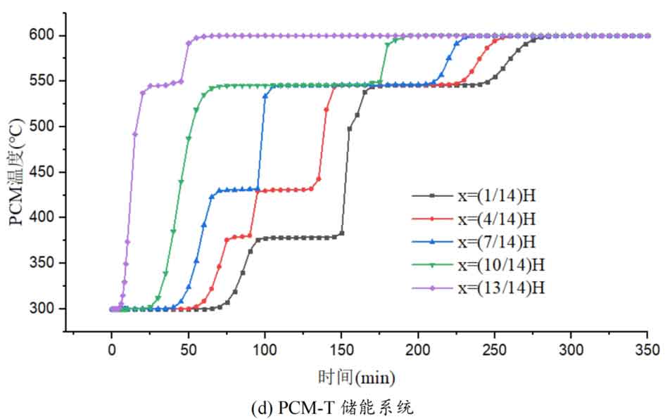
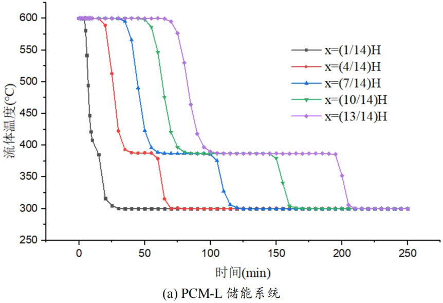
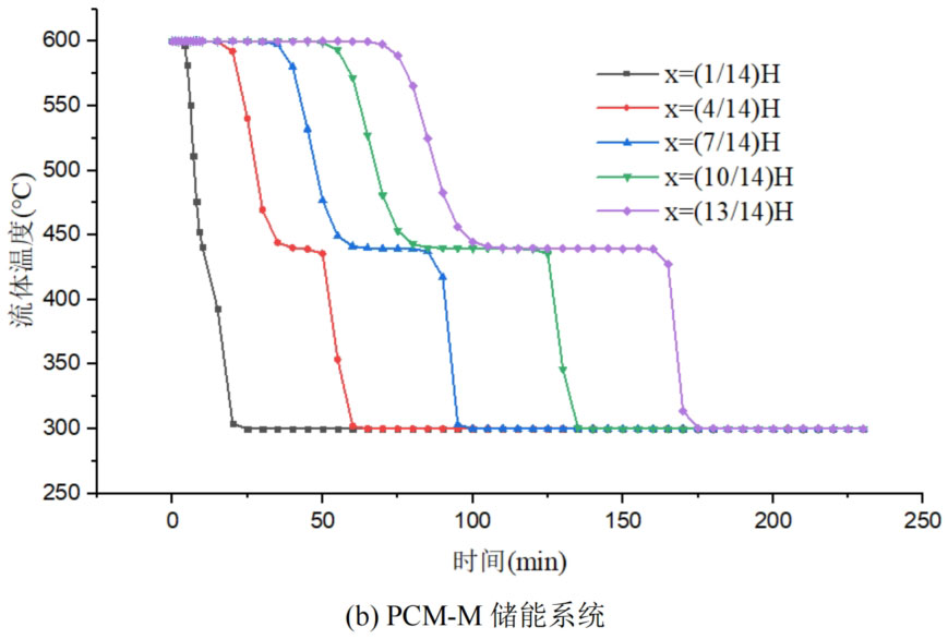
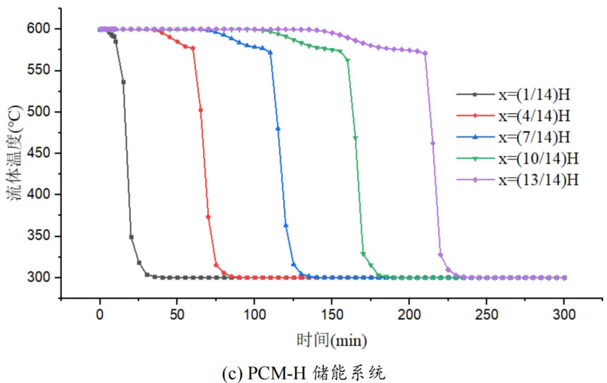
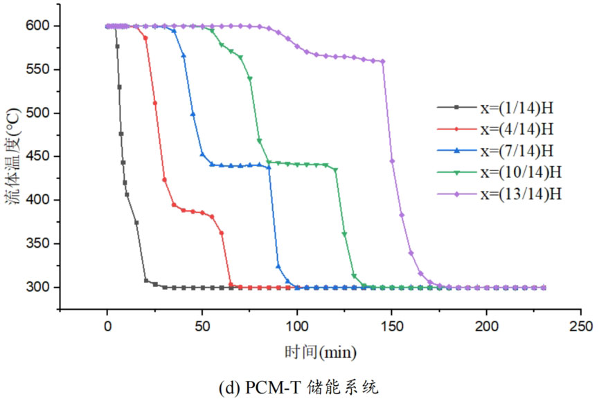
During the energy storage process, the initial temperature of the packed bed is 300 ℃, the inlet temperature of the fluid is 600 ℃, and the fluid flows in from the top of the tank (x=H) with an inlet flow rate of 0.03m/s. Figure 1 shows the temperature variation of phase change materials over time during the thermal storage process of four types of packed bed energy storage systems. The slope of the temperature curve of phase change materials represents the heat exchange rate between the fluid and the phase change materials. The larger the slope, the more sufficient the heat exchange, and the faster the energy storage speed of the system. Along the height direction of the tank, the closer to the top of the tank, the faster the temperature rise of the phase change material, and the shorter the time required for the complete melting of the phase change material. Therefore, the phase change constant temperature stage is also shorter. As the heat exchange process progresses, the phase change material at the bottom of the tank begins to heat up. The closer it is to the bottom of the tank, the smaller the fluid temperature and the smaller the temperature difference between the phase change material. The time required for the complete melting of the phase change material increases, and the duration of the phase change constant temperature stage increases.
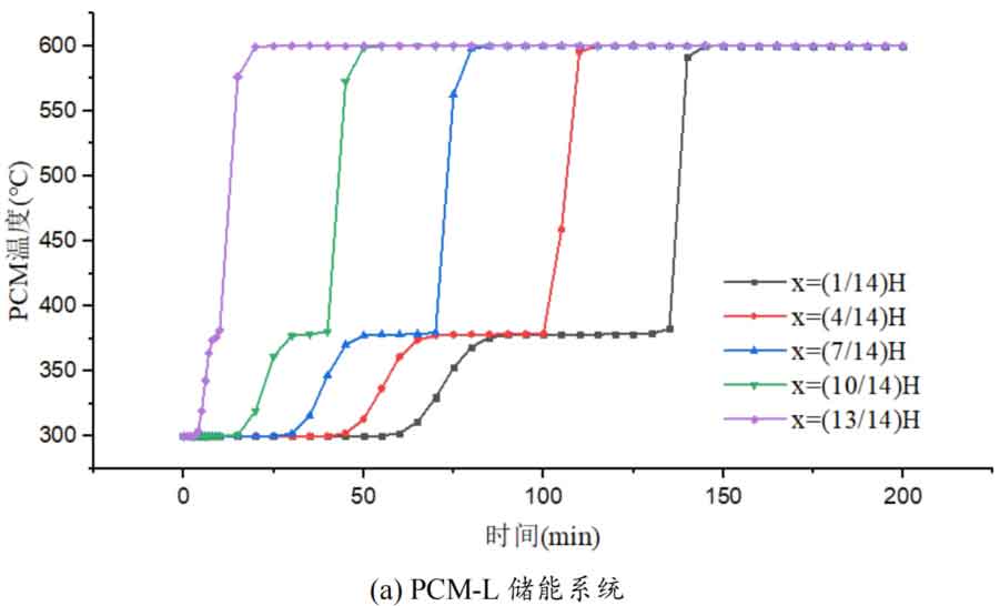
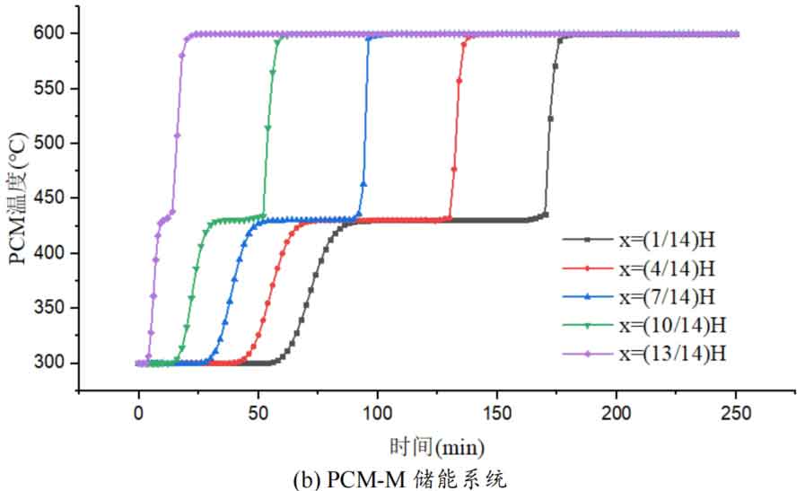
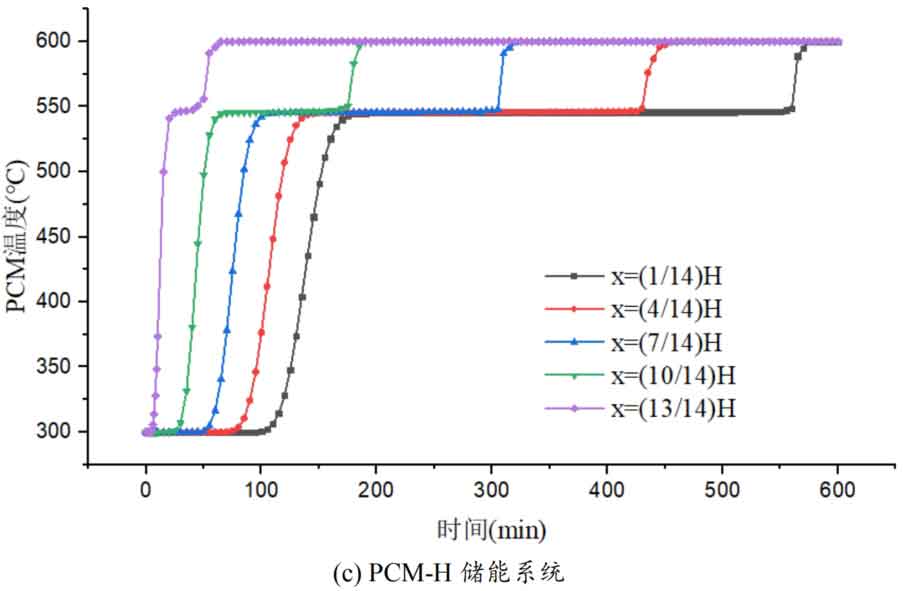
For a single phase change packed bed energy storage system, there are significant differences in heat transfer rates between fluids and phase change materials at different positions. Along the direction of fluid flow, as the heat transfer temperature of the fluid decreases, the heat transfer rate between the fluid and the phase change material decreases. However, for multi-layer phase change packed bed energy storage systems, the melting point of phase change materials decreases sequentially with the direction of fluid flow, which means that different temperature gradients of fluid heat can be utilized for heat storage. In this system, the difference in the duration of the phase change constant temperature stage at different positions is reduced, indicating an increase in heat transfer rate.
During the heat storage process, the time required for the phase change material to reach the final temperature at different positions in the energy storage system increases correspondingly as the phase change temperature of the phase change material increases. At the position x=(1/14) H, the temperature rise of the phase change material is the slowest. It takes 163 minutes for the PCM-L energy storage system to reach the final steady-state temperature, while the PCM-H energy storage system takes the longest time to reach the final steady-state temperature, which is 598 minutes. The heat transfer rates of the PCM-M unit and PCM-T unit are between the two, and they take 194 minutes and 289 minutes to reach the stable state, respectively. This is because the density and specific heat capacity of high-temperature phase change materials are the highest, and increasing the unit temperature requires more heat. Under the same conditions, compared to medium and low temperature phase change energy storage systems, the temperature rise of high-temperature phase change energy storage systems is relatively slow. At the same time, the melting point of high-temperature phase change materials is relatively high. When the temperature of phase change materials increases from the initial temperature to the phase change temperature, the duration of the phase change energy storage stage is longer due to the small temperature difference between the phase change temperature and the fluid temperature. Especially as it approaches the bottom of the tank, the temperature of the fluid decreases after heat exchange, and the phase change energy storage stage lasts longer. In contrast, the solid-state sensible heating stage of medium and low temperature phase change materials heats up quickly and reaches the phase change temperature after a short period of time. At this time, the temperature difference between the phase change temperature of the phase change material and the fluid is relatively large, so the phase change energy storage stage is also relatively short.
For a three-layer PCM-T energy storage system, the high-temperature phase change material at the top of the tank should be completely melted before the phase change energy storage stage disappears, so that the hot zone can move downwards along the filled bed. Therefore, setting relatively fewer high-temperature phase change materials at the top is more conducive to storing more heat at high operating temperatures. The bottom phase change material can serve as a buffer to prevent the phase change material from reaching a fully melted state too early. Compared to a single phase change energy storage system, in a three-layer PCM-T system, each layer of PCM can use fluids at different temperatures for energy storage. The energy storage rate of phase change materials is relatively high near the inlet of the tank, which helps to promote the energy storage process.
During the heat release process, the initial temperature of the packed bed is 600 ℃, the inlet temperature of the fluid is 300 ℃, and the low-temperature fluid flows in from the bottom of the tank (x=0) with an inlet flow rate of 0.03m/s. Along the height direction of the tank, the temperature difference between the phase change material at the bottom of the tank and the fluid is the highest, so the heat transfer rate between the two is the fastest. As the fluid is heated, the temperature difference between the fluid and the phase change material gradually decreases along the direction of fluid flow, leading to a decrease in heat transfer between them. From the temperature changes of fluids at different positions in the four energy storage systems, it can be seen that the closer they are to the top of the tank, the longer the duration of heat release, while the closer they are to the bottom of the tank, the higher the heat release rate. Similar to the heat storage process, the duration of latent heat released by phase change materials at different positions varies. Figure 2 shows the temperature variation of the heat transfer fluid over time during the heat release process of four different energy storage system units. The slope of the temperature curve of the heat transfer fluid represents the heat exchange rate between the fluid and the phase change material. During the heat release process, the performance of the three-layer PCM-T energy storage system is the best, and the time required for heat release to reach steady state is the shortest. At x=(13/14) H, the time for the fluid temperature to reach the set temperature is 178 minutes. One advantage of the PCM-T energy storage system is that it can provide a higher output power heat transfer fluid at the same time. Moreover, benefiting from the solidification heat release of high-temperature phase change materials at the top, they can be used for power generation under partial load conditions.
The change in liquid fraction is also an important indicator reflecting the thermal performance of the energy storage process in the system. Figures 3 and 4 respectively show the variation of the average liquid fraction of different energy storage systems over time during the heat storage and release processes. The average liquid fraction represents the proportion of liquid or solid phase change materials in the energy storage system unit. The slope of the curve represents the rate of change in the state of phase change materials during the heat storage or release process, with a larger slope indicating better dynamic performance.
At the initial stage of the heat storage process, all phase change materials in the system are in a solid state, with an average liquid fraction of 0. As the phase change material is heated and melted, the liquid fraction begins to increase until it is completely melted, and the average liquid fraction of the phase change material becomes 1. The exothermic process is exactly the opposite. At the initial moment, the phase change material is all in a liquid state, with an average liquid fraction of 1. As the phase change material solidifies and releases heat, it eventually becomes solid, with an average liquid fraction of 0.
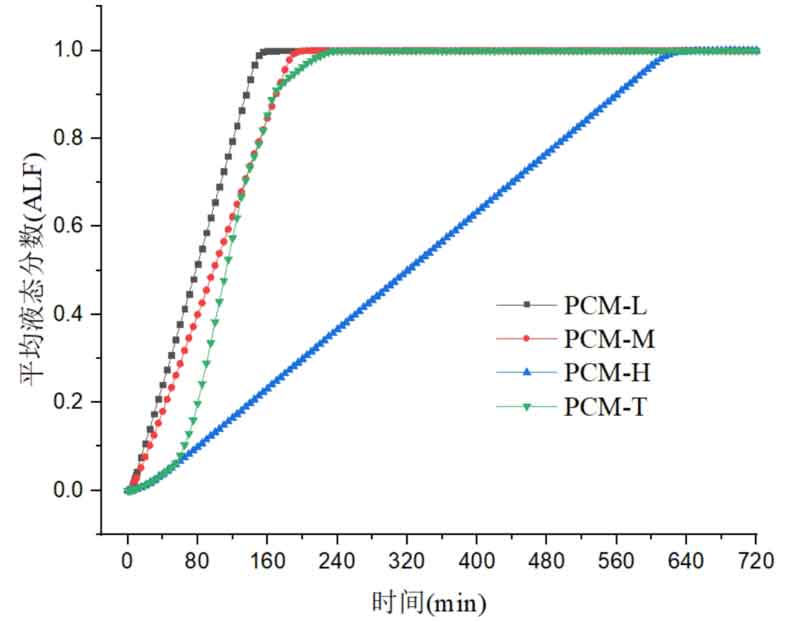
The variation of the average liquid fraction during the heat storage process is shown in Figure 3. From the slope size, the PCM-L system has the highest slope of the liquid fraction curve, while the PCM-H system has the lowest slope. This is because in the PCM-L energy storage system, the melting point of phase change materials is the lowest, and the difference between phase change temperature and fluid temperature is the largest. The phase change materials at the bottom of the tank can also exchange heat quickly even at lower fluid temperatures, so the time required for all phase change materials to melt in the system is the shortest. Due to the good matching between the phase change temperature of each phase change material and the temperature distribution of the heat transfer fluid in the three-layer PCM-T energy storage system, good energy storage effects can also be achieved. The top of the three-layer PCM-T energy storage system contains one-third of the high-temperature phase change material, which has a higher melting point, longer phase change energy storage time, and relatively lower heat transfer rate. Therefore, in the initial stage of the energy storage system, the average liquid fraction slope of the system is relatively small. As the fluid flows, the medium and low temperature phase change materials also begin to melt, the heat transfer rate accelerates, and the average liquid fraction slope of the energy storage system gradually increases, exceeding that of the PCM-M energy storage system. Because it takes longer for the high-temperature phase change material to completely melt, the slope of the liquid fraction decreases again before reaching the final state. The PCM H energy storage system requires the longest melting time for all phase change materials and the smallest average liquid fraction slope. This is because as the fluid heat transfer temperature decreases, it takes longer for the high-temperature phase change material at the bottom of the tank to melt. At the same time, due to the reduced temperature difference between the phase change material and the fluid, the heat transfer rate in the area closer to the bottom also decreases.
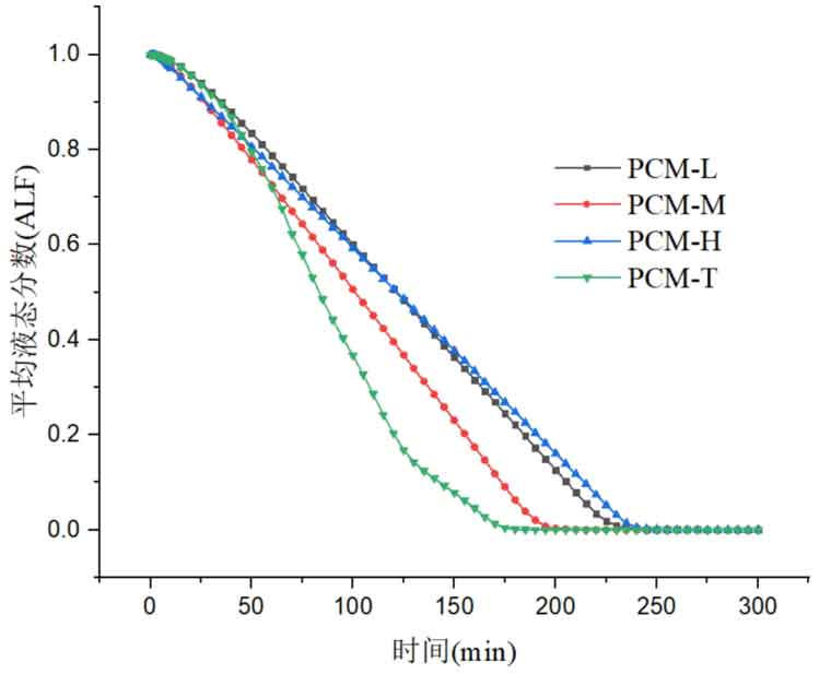
Figure 4 shows the variation of the average liquid fraction of four energy storage units during the exothermic process. From the graph, it can be seen that the three-layer PCM-T energy storage system has the best heat release performance, able to release all latent heat in a short period of time, and has a relatively high thermal response. PCM-H energy storage units have the worst heat release performance, and phase change materials require the longest time to release all latent heat. From the process of liquid fraction change, it can be seen that in the initial stage, the average liquid fraction slopes of the four energy storage units are not significantly different. After 65 minutes, the three-layer PCM-T system shows superiority, with a significant increase in heat release rate and slope. After 125 minutes, the slope of the liquid fraction curve decreases, indicating a decrease in the solidification rate of the phase change material and a slowdown in the heat release rate. The solidification rate of phase change materials in the other three energy storage units is relatively stable, and the heat release process is relatively stable.
2. The influence of different flow rates on the thermal storage performance of packed bed energy storage systems
In order to study the effect of heat transfer fluid velocity on the thermal storage performance of different packed bed systems, three operating conditions were selected: fluid velocity of 0.02m/s, 0.03m/s, and 0.04m/s. During the heat storage process, the inlet temperature of the heat transfer fluid is 600 ℃, and the initial temperature of the system is 300 ℃. Figure 5 shows the temperature changes of phase change materials at different positions in the energy storage system under different inlet flow rates. From the graph, it can be seen that as the fluid velocity increases, the heat storage time of all four energy storage systems decreases. This is mainly because the increase in flow rate strengthens the convective heat transfer between the heat transfer fluid and the phase change material, thereby accelerating the heating rate. Meanwhile, the larger the flow rate of the heat transfer fluid, the greater the temperature difference between the fluid and the phase change material, which is also beneficial for heat transfer. Overall, an increase in the flow rate of the heat transfer fluid promotes the heat storage process, increases the rate of heat storage, and thus shortens the heat storage time.

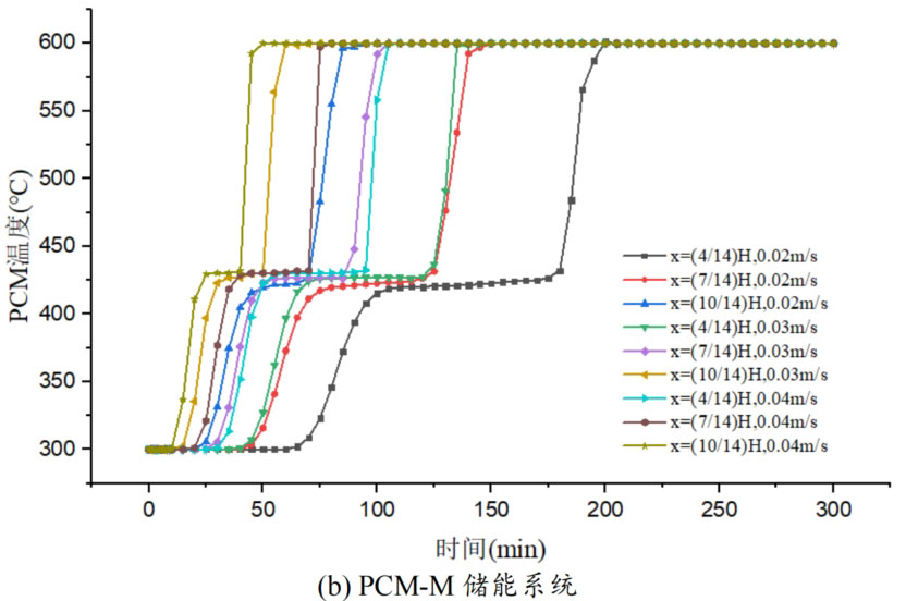
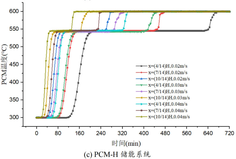
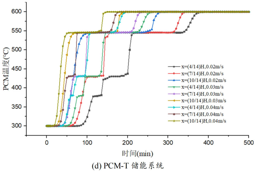
From Figure 5, it can be seen that when the operating temperature range of the energy storage system is relatively large, the influence of fluid flow rate changes on the temperature of phase change materials at different positions in the energy storage system can be divided into three processes: (1) solid-state sensible heat storage stage; (2) Phase change latent heat energy storage stage; (3) Liquid sensible heat energy storage stage. In the stage of solid-state sensible heat energy storage, in different energy storage systems, as the fluid flow rate increases, the slope of the temperature curve increases, and the temperature rise of phase change materials accelerates, indicating that enhanced convective heat transfer leads to an increase in heat transfer rate. In the phase change energy storage stage, as the flow rate increases, the phase change constant temperature stage in each energy storage system shortens. In the liquid sensible heat stage, there is little difference in the temperature rise rate of phase change materials under different flow rates.
The heat transfer rate of energy storage systems is related to the material location and fluid flow rate. The closer to the inlet of the tank, the higher the fluid temperature, the greater the temperature difference between the fluid and the phase change material, and the larger the slope of the temperature curve, resulting in a relatively high heat transfer rate and a shorter time required to reach the set temperature. Comparing the three energy storage systems, PCM-L, PCM-M, and PCM-H, the energy storage time increases sequentially. From the influence of different flow rates on heat transfer rate, it can be seen that at the x=(4/14) H position, the fluid temperature is lower and the temperature rise of phase change materials is slower. When the fluid velocity increased from 0.02m/s to 0.04m/s, the solid-state sensible heat stage time of PCM-L, PCM-M, and PCM-H energy storage systems was shortened by 49.0%, 52.4%, and 47.5%, respectively. The phase change energy storage stage time was shortened by 53.6%, 38.4%, and 50.6%, respectively, while the liquid sensible heat stage time was shortened by 28.6%, 21.9%, and 16.7%, respectively. The increase in flow rate and the decrease in heat storage time are mainly reflected in the solid-state sensible heat stage and the phase change latent heat stage, with a relatively small effect on the liquid energy storage stage. For the PCM-T system, due to the setting of phase change materials with different phase change temperatures in the tank, different levels of phase change materials can use fluids at different temperatures for heat storage during fluid flow heat transfer. The flow rate increases from 0.02m/s to 0.04m/s, and the heat storage time is shortened by 48.9% at the x=(4/14) H position.
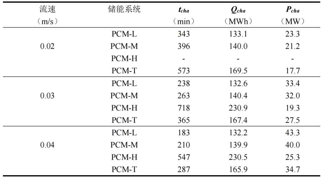
Table 1 shows the thermal storage performance indicators of four energy storage systems under different flow rates. From the results, it can be seen that under different flow rate conditions, the difference in heat transfer from the fluid to the energy storage unit is small for the same energy storage system, and an increase in flow rate does not significantly affect the heat transfer from the fluid to the energy storage system. However, an increase in flow rate can significantly reduce the system’s heat storage time and improve the energy storage rate. Taking the PCM-T system as an example, when the fluid flow rate increases from 0.02m/s to 0.04m/s, the heat storage time decreases by 36.3% and 21.4% respectively. This is because as the flow rate increases, the convective heat transfer ability between the fluid and the phase change material increases, and the accelerated heat transfer reduces the system’s heat storage time. As the fluid flow rate increases, the energy storage rate of the PCM-T energy storage system unit also increases. The energy storage rate increased from 17.7MW at 0.02m/s to 34.7MW at 0.04m/s, with a growth rate of 96.05%. This is mainly due to the reduced heat storage time of the energy storage system caused by the increase in flow velocity. Although the PCM-H energy storage system unit receives the most heat from the fluid, its heat storage time is also the longest, resulting in the lowest energy storage rate. As the flow rate increased from 0.03m/s to 0.04m/s, the system energy storage rate increased to 25.3MW, an increase of 31.1%.
Comparing the thermal storage performance of different energy storage system units, it was found that for a single phase change material energy storage system, as the phase change temperature of the phase change material increases, the system’s thermal storage time increases, and the heat transferred from the fluid to the energy storage system also increases. The heat storage time of PCM-T energy storage system is higher than that of PCM-L and PCM-M energy storage systems, but it is shorter than that of PCM-H unit. This is mainly because the more high-temperature phase change materials there are, the longer it takes for them to completely melt. In terms of the heat transferred from the fluid to the energy storage system, the PCM-H energy storage system is the largest, followed by the PCM-T system, and the low-temperature PCM-L system is the least. From equations (4-37), it can be seen that this is mainly related to the thermal properties of the heat transfer fluid, the system heat storage time, the fluid flow rate, and the temperature difference between the fluid inlet and outlet. The more high-temperature phase change materials there are, the longer the heat storage time of the system, and the more energy is obtained from the fluid.
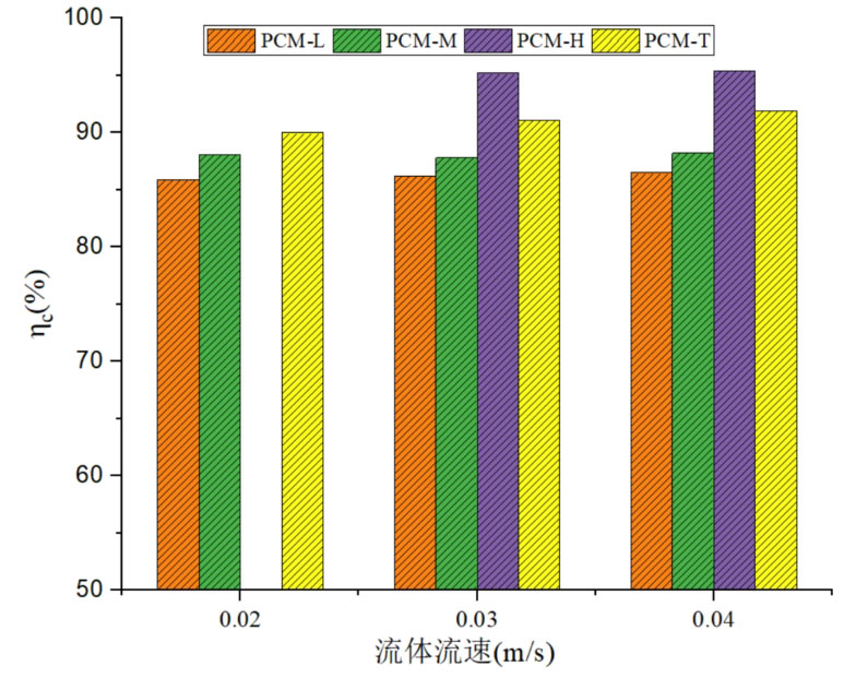
Figure 6 shows the comparison of energy storage efficiency of four energy storage systems at different fluid velocities. As the fluid flow rate increases, there is no significant difference in energy storage efficiency among different energy storage system units. From the perspective of energy storage efficiency, the PCM-H system has the highest energy storage efficiency, followed by the PCM-T system, and the PCM-L system has the lowest energy storage efficiency. For PCM-L and PCM-T systems, as the fluid velocity increases, the energy storage efficiency monotonically increases, but the increase is relatively small. The energy storage efficiency of PCM-L unit increased from 85.9% at 0.02m/s to 86.5% at 0.04m/s, while the energy storage efficiency of PCM-T unit increased from 90.0% to 91.9%, with an increase of 1.9%. By increasing the fluid flow rate, there was no significant change in the energy storage efficiency of the energy storage system. This is because the fluid flow rate mainly affects the heat transfer rate between the heat transfer fluid and the heat storage medium, and the increase in flow rate does not significantly affect the heat transfer from the fluid to the system. Therefore, the impact on the energy storage efficiency of the system is relatively small.
3. The impact of different operating temperature ranges on the thermal storage performance of the system
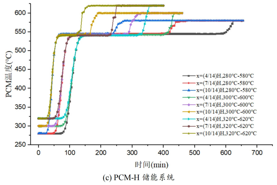
Due to the temperature dependent thermal properties of the heat transfer fluid, the thermal storage performance of the system is affected by the fluid temperature. Therefore, the operating temperature range (Tini Tin) also affects the thermal storage performance of the energy storage system. In order to study the effect of different working temperature ranges on the thermal storage performance of phase change packed beds, three working temperature ranges were selected: 280 ℃ -580 ℃, 300 ℃ -600 ℃, and 320 ℃ -620 ℃, with a fluid velocity of 0.03m/s. Figure 7 shows the temperature variation of phase change materials over time in four energy storage systems under different operating temperature ranges. From the graph, it can be seen that the four energy storage systems have the same pattern. As the working temperature range increases, the time required for the phase change material temperature to reach the set temperature decreases at the same position of the energy storage system unit.
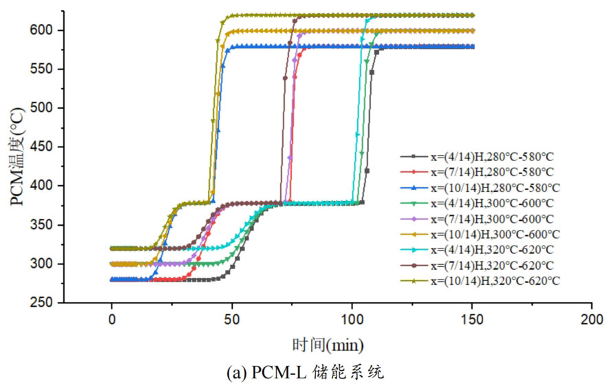
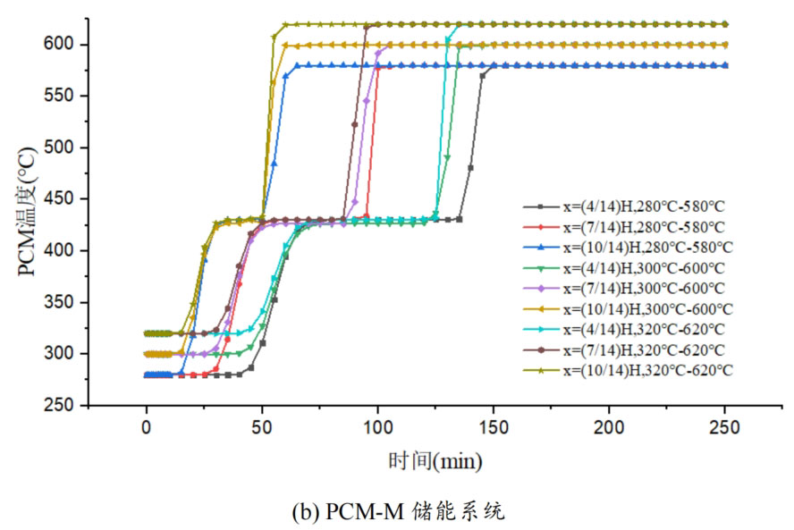
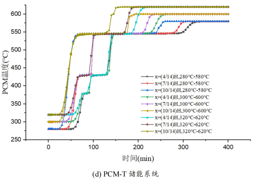
In the solid-state sensible heat storage stage, as the working temperature range increases, although the fluid inlet temperature is higher, the temperature difference between the fluid and the phase change material at the initial moment is certain, which has a relatively small impact on the heat transfer rate between them. From the graph, it can be seen that as the working temperature range increases, there is no significant difference in the heating rate of phase change materials during the sensible heat stage.
In the phase change energy storage stage, as the working temperature range increases, the duration of the phase change energy storage stage decreases, indicating an increase in heat transfer rate between the phase change material and the heat transfer fluid. This is because, although the temperature difference between the fluid and the phase change material remains constant at the initial time, as the operating temperature range increases, the inflow temperature of the fluid increases, and the temperature difference with the phase change temperature increases. Moreover, from the formula, it can be seen that the thermal conductivity of the fluid also increases with increasing temperature, resulting in faster heat transfer between them and shorter time required for the complete melting of phase change materials.
As the phase change temperature of the phase change material increases, the effect of the higher operating temperature range on reducing the time of the phase change heat storage stage becomes more apparent. Taking the high-temperature energy storage system unit PCM-H as an example, there are three operating temperature ranges from low to high. At the x=(4/14) H position of the energy storage system unit, the time of the phase change latent heat storage stage is 465 minutes, 270 minutes, and 185 minutes, respectively. Compared to the lower operating temperature range, the phase change heat storage stage time in the higher operating temperature range was reduced by 41.9% and 60.2%, respectively. However, the effect of reducing phase change heat storage time follows a decreasing marginal effect. The higher the working temperature range, the smaller the effect of this effect. From the range of 300 ℃ -600 ℃ to the range of 320 ℃ -620 ℃, the phase change heat storage time decreases by only 31.5%. At the x=(10/14) H position of the energy storage system unit, the time required for the complete melting of phase change materials is 175 minutes, 100 minutes, and 65 minutes, respectively. Compared to the lower operating temperature range, the phase change heat storage time in the higher operating temperature range decreased by 42.9% and 62.9%, respectively, indicating that the effect of this effect is not significantly different at the two positions.
In the stage of liquid sensible heat storage, there is no significant difference in the heating rate of phase change materials under different operating temperature ranges. The closer to the inlet, the greater the slope of the temperature curve of the phase change material, and the faster the heating rate of the phase change material. This is mainly because the fluid temperature is higher and the heat transfer is faster at the position close to the inlet.
Overall, a higher operating temperature range can improve the heat transfer rate between the fluid and phase change materials, and reduce energy storage time. However, the enhancement effect is mainly reflected in the phase change heat storage stage. In the other two stages, increasing the operating temperature range also has a certain improvement effect on the heat transfer rate, but the difference between them is relatively small.
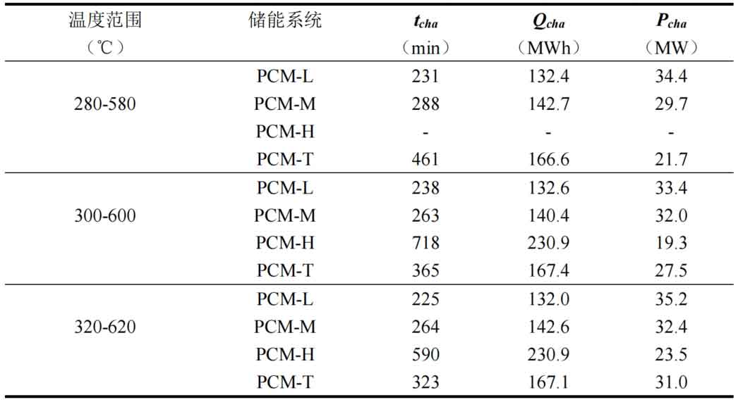
Table 2 compares the thermal storage performance of four energy storage systems under different operating temperature ranges. From the results, it can be seen that as the working temperature range increases, the heat storage time of different energy storage systems decreases, but the impact on the PCM-L system is relatively small. This is because the thermal conductivity of the fluid increases with increasing temperature. Meanwhile, the higher the inlet temperature, the higher the energy storage rate of the system. Taking the PCM-T energy storage system unit as an example, the energy storage rate is 21.7MW when the operating temperature range is between 280 ℃ and 580 ℃. When the working temperature range is between 320 ℃ and 620 ℃, the energy storage rate is 31.0MW, which increases by 42.9%. Meanwhile, the system’s heat storage time decreased from 461 minutes to 323 minutes, a decrease of 29.9%. This indicates that in the high operating temperature range, fluid and phase change heat storage materials exchange heat faster.
The difference in heat transfer from fluid to energy storage system units is small across different operating temperature ranges. However, as the operating temperature range increases, the system’s heat storage time decreases and the energy storage rate correspondingly increases. The effect of increasing the working temperature range on improving the energy storage rate is smaller than that of increasing the flow rate. This is mainly because an increase in flow rate has a stronger effect on reducing the system’s heat storage time. When the heat transfer from the fluid to the system is not significantly different, the effect of flow rate on the system’s energy storage rate should be greater.
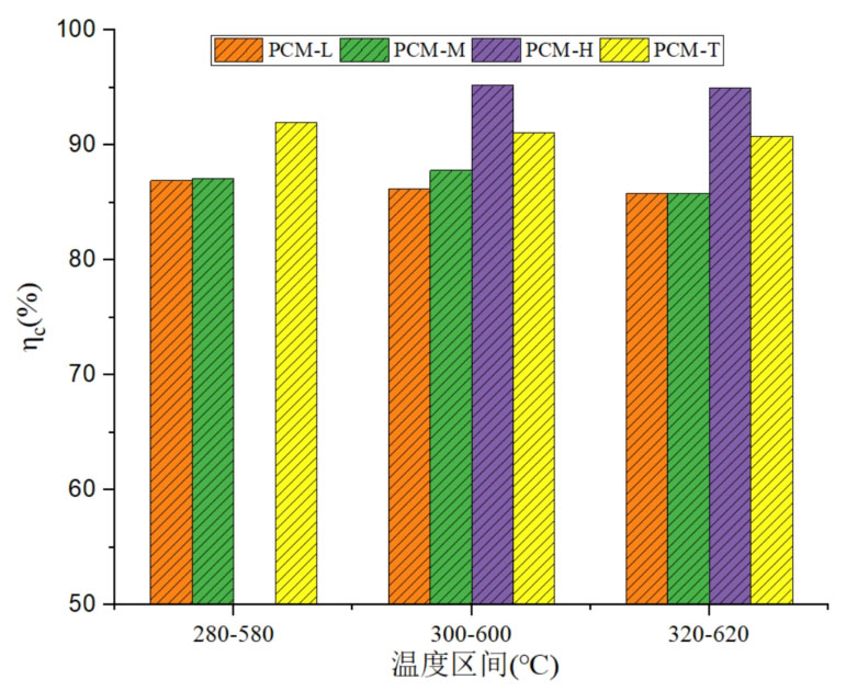
Figure 8 compares the energy storage efficiency of four energy storage units under different operating temperature ranges during the heat storage process. From the graph, it can be seen that there is a significant difference in energy storage efficiency between different energy storage systems. As the phase change temperature increases, the energy storage efficiency of the system increases. PCM-H has the highest energy storage efficiency, while the energy storage efficiency of the three-layer PCM-T energy storage system is higher than that of the medium and low temperature phase change energy storage systems. As the working temperature range increases, there is no significant change in the energy storage efficiency of the same energy storage system. Moreover, as the working temperature range increases, there is a slight downward trend in thermal storage efficiency.
4. The influence of the proportion of phase change materials on the thermal storage performance of the system
The above compares the thermal performance of a single phase change packed bed thermal storage system and a three-layer phase change packed bed thermal storage system. However, there is relatively little research on the impact of the volume fraction of phase change materials in each layer on the thermal storage performance in a three-layer phase-change packed bed energy storage system. Three types of phase change materials with different phase change temperatures are used as energy storage media, which are arranged sequentially in various parts of a vertical tank. Table 3 presents the volume fraction of three-layer phase change materials for different packed bed energy storage units, with the total volume of several combinations of phase change materials in each tank being the same.
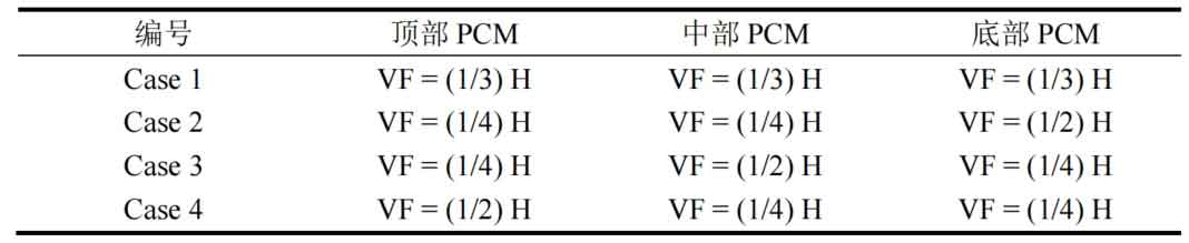
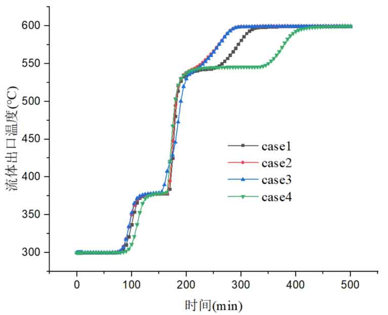
Figure 9 shows the time variation curve of fluid outlet temperature in energy storage systems under four different proportions of phase change materials. From the graph, it can be seen that the heat storage process in Case 4 takes the longest time, followed by Case 1. The time required for the heat storage process in Case 2 and Case 3 is basically the same. This is mainly because in Case 4, the proportion of high-temperature phase change materials is the highest. The high-temperature phase change materials are arranged at the top of the tank. Although they first exchange heat with the heat transfer fluid and begin to melt as the temperature increases, their melting point is higher, and it takes longer for the high-temperature phase change materials to completely melt. The proportion of high-temperature phase change materials in Case 1 is also relatively large, so it takes a longer time for complete melting. As the fluid continues to flow along the tank, it exchanges heat with the phase change materials in each layer. When the molten salt reaches the bottom, the low-temperature phase change material is heated and begins to melt, and the melting rate is higher than that of the high-temperature phase change material. This can also be explained by the change in the average liquid fraction in the tank. From the figure, it can also be seen that in Case 3, due to the large proportion of medium temperature phase change materials, the fluid outflow temperature has a slower heating rate in the middle time period, which indicates that in this case, it takes longer for the medium temperature phase change materials to completely melt. Near the high-temperature phase change temperature, in four cases, as the proportion of high-temperature phase change materials increases, the time for the fluid to flow out at high temperature and constant temperature increases. This indicates that as the proportion of high-temperature phase change materials increases, the time required for their complete melting is longer, resulting in longer fluid constant temperature flow out time. After the high-temperature phase change material is completely melted, the outflow temperature continues to rise, and the time required for the system to reach its final state also increases.
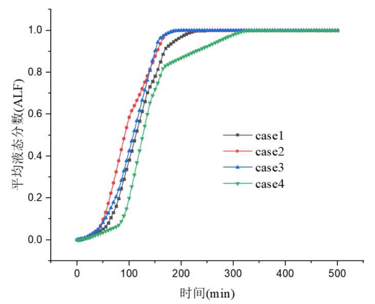
Figure 10 shows the variation of the average liquid fraction of phase change materials over time. The melting time for all phase change materials in Case 2 is the shortest, followed by Case 3. Among them, Case 2 has the highest proportion of low-temperature phase change materials, Case 3 has the highest proportion of medium temperature phase change materials, and in both cases, the proportion of high-temperature phase change materials is relatively small. This indicates that the larger the proportion of high-temperature phase change materials, the longer it takes for them to fully melt. Although high-temperature phase change materials are arranged at the top to first exchange heat with the heat transfer fluid, due to the large temperature difference between the phase change temperature and the fluid of medium and low temperature phase change materials, they will use fluids at different temperatures for heat storage. As a result, the larger the proportion of medium and low temperature phase change materials, the shorter the total melting time of the phase change materials. In Case 4, the melting time of all phase change materials is the longest, indicating that in Case 4, after all the medium and low temperature phase change materials are melted, the high temperature phase change materials at the top have not been completely melted. From the Case 4 curve in Figure 10, it can also be seen that in the initial stage, the melting rate of the high-temperature phase change material at the top is slow, and after 100 minutes, the melting rate increases, indicating that during this period, the low-temperature phase change material begins to melt in large quantities, and the average liquid fraction of the entire system increases rapidly. However, after 175 minutes, the slope of the average liquid fraction curve of the system decreased again, indicating that during this period, the remaining high-temperature phase change materials were mainly melted, and the melting rate was slower.
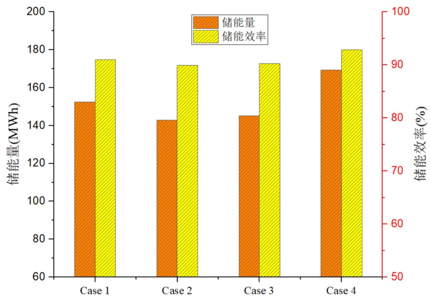
The influence of the volume fraction of phase change materials on the energy storage efficiency of energy storage systems is shown in Figure 11. Case 4 has the highest energy storage efficiency, with a storage efficiency of 92.9%. At the same time, the energy storage unit in Case 4 also has the highest energy storage, with a storage capacity of 169.36 MWh. Next is Case 1, which has an energy storage efficiency of 91.0% and a heat storage capacity of 152.51 MWh. Next are Case 3 and Case 2, with energy storage efficiency of 90.3% and 89.9% respectively, and energy storage of 145.22 MWh and 142.96 MWh, respectively. Overall, as the volume of high-temperature phase change materials increases, the system’s energy storage and energy storage efficiency both increase sequentially. However, there is not much difference in energy storage efficiency among several different volume fractions, and the difference in energy storage efficiency between them is smaller than that between a single phase change energy storage system and a cascaded phase change energy storage system. This indicates that the impact of different phase change material volume ratios on energy storage efficiency is relatively small.
Figure 12 shows the comparison of system energy storage rate and fluid heat transfer under different volume fractions. From the graph, it can be seen that Case 4, which has the highest proportion of high-temperature phase change materials, transfers the most heat, reaching 182.39 MWh, followed by Case 1, Case 3, and Case 2. In Case 2, due to the largest proportion of low-temperature phase change materials, the heat obtained is the least. Although Case 4 has a high energy storage efficiency, its energy storage rate is relatively low. From the comparison of energy storage rates under different volume fractions in Figure 12, it can be found that Case 4 has the lowest energy storage rate, which is 24.0MW, significantly lower than the other three cases. The difference in energy storage rates among the other three scenarios is not significant, with energy storage rates increasing by 14.6%, 22.9%, and 25.0% compared to Case 4, Case 1, Case 2, and Case 3, respectively. This indicates that as the proportion of high-temperature phase change materials increases, although the heat transferred from the fluid to the phase change materials increases, it takes longer for the phase change materials to completely melt, which leads to a decrease in their energy storage rate.
5. Analysis of thermal storage performance of sensible latent heat combined packed bed system
Solid filling materials can reduce the amount of molten salt used in a single tank molten salt energy storage system. However, due to their lower energy storage density, phase change materials with higher energy density are used to replace some solid filling materials, forming a multi-layer sensible latent heat combined packed bed energy storage system. Compared to a single phase change packed bed energy storage system, it uses fewer phase change materials and reduces packaging costs, which can save investment costs without significantly reducing energy storage performance.
In the sensible latent heat combined heat storage system, the energy storage medium is either sensible heat material or phase change material, and the phase change temperature of the phase change material is selected within the allowable temperature range. For a three-layer sensible latent heat combined heat storage system, phase change materials with higher melting points are selected and placed at the top of the tank, solid sensible heat materials are set in the middle layer, and phase change materials with lower melting points are set at the bottom of the tank. Phase change materials can not only increase the energy storage capacity of energy storage units, but also keep the temperature of the flowing fluid within the allowable range, playing a certain buffering role.
This model uses high-temperature concrete as a solid sensible heat material and sets up four forms of sensible latent heat energy storage systems, namely C-PCM, C-G2, C-PCM3, and C-PCM4. The high-temperature concrete solid material is placed in the middle of the tank, accounting for 1/3, 50%, 60%, and 70% of the total volume of the tank, and phase change materials with the same volume fraction are set at both ends. Compare the energy storage, storage rate, and storage efficiency of sensible latent heat energy storage systems with different volume ratios.
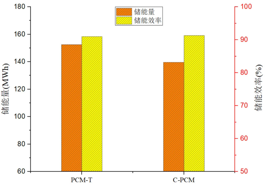
Figure 13 shows the comparison of thermal storage performance between PCM-T energy storage system and C-PCM energy storage system. From the size of energy storage, it can be seen that the energy storage of PCM-T system is higher than that of C-PCM system, with the former being 8.5% higher than the latter. This indicates that phase change materials have stronger energy storage capacity than concrete during the heat storage process, with a higher energy storage density per unit volume. However, from the comparison of the energy storage efficiency of the two energy storage systems, they are 91.0% and 91.3% respectively. The energy storage efficiency of the concrete system has increased, but the increase is small. This indicates that the use of concrete filling materials instead of partial phase change materials mainly affects the thermal storage performance of the system in terms of energy storage, and has a relatively small impact on energy storage efficiency.
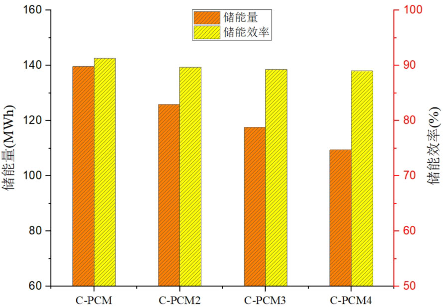
In order to compare the effects of different concrete volume fractions on the thermal storage performance of the system, the energy storage and energy storage efficiency of four types of sensible latent heat combined energy storage systems were calculated. The comparison between them is shown in Figure 14. From the graph, it can be seen that as the proportion of concrete volume increases, the energy storage capacity of the energy storage system decreases. C-PCM has the highest energy storage, which is 9.8%, 15.8%, and 21.7% higher than C-PCM, C-PCM3, and C-PCM4, respectively. This indicates that the concrete volume ratio is inversely proportional to the system’s energy storage. From the energy storage efficiency, it can be seen that as the volume ratio of concrete increases, the thermal storage efficiency decreases, but the decrease is very small. As the volume ratio of concrete increases, although the energy storage of the system and the heat transferred by the fluid to the system decrease, their reduction ratio is equivalent, resulting in a small change in energy storage efficiency. Among the four scenarios, the maximum energy storage efficiency of the C-PCM system is 91.3%, and the minimum energy storage efficiency of the C-PCM4 system is 89.0%, but the difference between the two is relatively small.
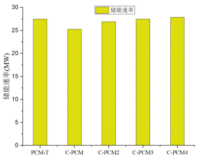
Figure 15 shows a comparison of energy storage rates for different energy storage systems. For the sensible latent heat combination system, as the volume ratio of concrete increases, the energy storage rate of the system increases. This is because, although as the volume ratio of concrete increases, the heat transfer from the fluid to the energy storage system decreases. However, the thermal conductivity of concrete is relatively high, and the larger the volume ratio of concrete, the shorter the overall heat storage time of the system. Under the combined effect of both, as the volume ratio of concrete increases, the energy storage rate of the system increases. Comparing the energy storage rates of PCM-T system and C-PCM system, it can be seen that although concrete replaces some phase change materials, the C-PCM energy storage system is improved.
6. Summary
The transient heat transfer process of single and cascaded phase change packed bed energy storage systems was studied using a two-phase continuous model and local non thermal equilibrium theory. By using encapsulated phase change materials as energy storage media and using numerical simulation methods, the heat transfer behavior and phase change energy storage process between molten salt fluid and phase change spheres were studied. At the same time, the thermal storage performance of different energy storage systems was compared, and the effects of flow rate and operating temperature range on the thermal storage performance of energy storage systems with different configurations were analyzed. In addition, in order to reduce the investment cost of the system, an energy storage system combining sensible heat and latent heat was adopted, and the influence of different concrete volume ratios on the thermal storage performance of the system was analyzed. The main conclusions are as follows:
(1) Obtained the transient temperature variation law of the packed bed energy storage system. During the heat storage process, the temperature curves of the phase-change packed bed energy storage system exhibit different characteristics at different heights, and the heating rate is faster at positions closer to the inlet. When x/H is large (closer to the top), the temperature rise of phase change materials basically increases linearly. As x/H decreases (closer to the bottom), the heating rate of phase change materials slows down and the heating time becomes longer. When the phase change temperature is reached, the heating rate is almost zero. After the phase change heat storage stage is completed, the heating rate increases until the heat storage is completed.
(2) As the phase change temperature of the phase change material increases, the heat storage time of the system increases. The low-temperature PCM-L system has the shortest phase change energy storage stage due to the large temperature difference between the phase change temperature and the fluid temperature. The heat storage time of the three-layer PCM-T system is between PCM-M and PCM-H energy storage systems. During the heat storage process, the temperature distribution of the heat transfer fluid along the tank body matches well with the melting temperature of each layer of PCM.
(3) The effects of fluid flow rate and operating temperature range on different thermal performance indicators of phase change packed bed energy storage systems were obtained. Increasing the fluid flow rate and operating temperature range can both improve the energy storage rate of energy storage systems, but their impact on energy storage efficiency is relatively small. For a three-layer PCM-T energy storage system, when the fluid velocity increases from 0.02m/s to 0.04m/s, the energy storage rate increases by 96.0%. The increase in flow rate mainly improves the heat transfer rate between the fluid and phase change materials, while a higher operating temperature range increases the temperature difference between the inlet temperature and phase change temperature, which is beneficial for improving the energy storage rate. The increase in flow rate has a greater effect on improving the energy storage rate of the system than the increase in the working temperature range, mainly because the effect of reducing the system’s heat storage time is more pronounced with the increase in flow rate.
(4) In a three-layer phase-change packed bed energy storage system, as the volume proportion of high-temperature phase-change materials increases, the system’s energy storage and heat acquisition from the fluid increase, but the energy storage rate decreases. This is mainly because the more high-temperature phase-change materials there are, the longer the system’s heat storage time. However, the impact of different volume ratios of phase change materials on energy storage efficiency is relatively small.
(5) In the sensible latent heat combined packed bed energy storage system, as the proportion of concrete volume increases, the energy storage in the system decreases more significantly and the energy storage rate increases, but the change in energy storage efficiency is relatively small.