
The single tank filled bed energy storage system has a simpler structure compared to the traditional double tank molten salt energy storage system, which reduces the cost of the tank body. The single tank filled bed energy storage system uses encapsulated phase change materials with higher energy density to replace some molten salts, thereby improving the energy storage density of the system. It is increasingly receiving attention in the field of solar thermal power generation. The energy storage effect of a single tank filled bed energy storage system is closely related to geometric structure, operating parameters, energy storage medium, and heat transfer fluid. Therefore, it is necessary to establish a model of a single tank filled bed energy storage system, analyze the heat transfer process and the impact of influencing factors on the thermal performance of the system, which is essential for revealing the energy storage mechanism of a single tank filled bed system.
In a packed bed energy storage system, the heat transfer rate decreases with the use of a single phase change material as the fluid exchanges heat. In order to efficiently utilize fluid heat, phase change materials with different phase change temperatures are arranged along the direction of fluid flow, which can utilize the heat of heat transfer fluids at different temperatures for energy storage. This chapter analyzes the energy storage effect of a packed bed system using three-layer phase change materials based on a single phase change material. In addition, the volume fraction of phase change materials in each layer is different, and the impact on the thermal performance of the packed bed energy storage system will also vary. Therefore, it is necessary to determine the impact of their volume ratio on the energy storage efficiency of the system.
In order to balance energy storage and cost factors, it is considered to use concrete to replace some phase change materials, reducing the energy storage cost of the system while minimizing the impact of energy storage. At the same time, evaluate the impact of the proportion of material volume on the energy storage efficiency of the system, providing a basis for optimizing the energy storage system.
Based on the theory of local non thermal equilibrium in porous media and the theory of phase change heat transfer, the flow and heat transfer characteristics of heat transfer fluids in packed bed energy storage systems were studied, revealing the mechanism of interaction between heat transfer fluids and phase change energy storage media. The model also considers the influence of temperature changes on the thermal properties of heat transfer fluids. By analyzing the calculation results of the model, the thermal performance of the system during energy storage was evaluated, and the influence of fluid flow rate, operating temperature range, phase change material volume ratio, and solid filling material volume ratio on the thermal performance of different packed bed energy storage systems was clarified.
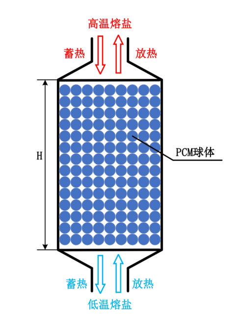
The model of a single tank filled bed phase change energy storage system is shown in Figure 1. The phase change spheres inside the simulation are considered as porous media, which come into contact and support each other, forming the skeleton of the thermal storage medium. The heat transfer fluid flows and transfers heat from the gaps. Under high temperature conditions, due to the relatively stable thermal properties of only molten salt, molten salt is chosen as the heat transfer fluid. In order to reduce the corrosion of molten salt on the encapsulated sphere, stainless steel material is used for the encapsulated sphere, and the surface is treated with an aluminum oxide coating.
During the heat storage process, at the initial moment, the molten salt fluid and phase change sphere in the energy storage system are in a low-temperature state. The high-temperature molten salt flows in from the top of the tank and exchanges heat with the internal energy storage medium, transferring heat to the phase change material. The low-temperature molten salt flows out from the bottom. During the heat release process, at the initial moment, the phase change material and molten salt in the energy storage system are in a high-temperature state. The low-temperature molten salt flows in from the bottom of the tank and exchanges heat with the high-temperature phase change material in the tank. The molten salt fluid is heated and the temperature rises, and the high-temperature molten salt flows out from the top of the tank.
The heat transfer mechanism of phase change packed bed energy storage system can be divided into: (1) heat transfer fluid and surface heat transfer of phase change sphere; (2) Heat transfer inside solid particles; (3) Heat exchange between the tank body and the surrounding environment.
(1) Molten salt fluid and surface heat transfer of encapsulated phase change materials. This process includes heat conduction of the heat transfer fluid during the flow process, convective heat transfer between the heat transfer fluid and the phase change sphere, heat conduction of solid particles through point contact, and radiative heat dissipation towards the surrounding area. In these processes, the dominant factor is the convective heat transfer between the heat transfer fluid and the phase change sphere. At the same time, the packed bed energy storage system has a large heat exchange area and excellent heat transfer capacity inside, which means that the phase change material particles increase the fluid resistance during the flow heat transfer process, resulting in a certain pressure loss of the fluid during the flow process.
(2) Heat transfer inside the phase change sphere. Due to the filling of phase change materials inside the sphere, the fluid transfers heat through the surface of the encapsulation material, and then the heat is transferred to the internal phase change material. During the heat storage process, the phase change material begins to be in a solid state. As the fluid transfers heat, the phase change material heats up. When the temperature of the phase change material reaches the phase change temperature, it begins to melt, and some of the phase change materials become liquid. This stage is a solid-liquid coexistence state, where the temperature change is within a small range, and the heat is stored in the form of latent heat. As the temperature further increases, all phase change materials melt, and at this point, heat is stored in the form of liquid sensible heat. There are multiple physical processes in the heat transfer process, such as fluid flow, convective heat transfer, and the boundary of phase change materials that need to be solved.
(3) The filling bed tank dissipates heat to the surrounding environment. There are multiple heat transfer methods near the inner wall of the tank. Firstly, the heat transfer fluid transfers heat to the walls of the tank through convective heat transfer and thermal conduction. The encapsulated sphere is in contact with the inner wall surface and transfers heat through thermal conduction. Due to the relatively high working temperature, the sphere can also transfer heat to the inner wall through radiation, and this type of radiation heat transfer is currently relatively less considered in research. Secondly, the inner wall of the tank also transfers heat to the outer wall through thermal conduction, which in turn conducts convective heat exchange with the surrounding air, resulting in partial heat loss of the energy storage unit. To reduce this loss, the general approach is to add insulation materials on the outer wall to minimize heat loss and improve the thermal efficiency of the energy storage system.
| Parameters | Size |
| Can body height (?) | 14m |
| Can body diameter (?) | 6.6m |
| Void rate (?) | 0.22 |
| Diameter of phase change sphere (?p) | 0.02 |
| Thickness of phase change sphere shell | 0.0005m |
| Tank thickness | 0.05m |
| Thickness of insulation layer material | 0.5m |
| Thermal conductivity of insulation layer | 0.039W/(m · K) |
| Heat transfer fluid velocity (?) | 0.03m/s |
| Heat transfer fluid (HTF) | 60% NaNO3&40% KNO3 |
| Phase change materials (PCM) | PCM-L, PCM-M, PCM-H |
| Working temperature range | 300 ℃ -600 ℃ |
The interior of the packed bed energy storage system is composed of phase change spheres with a diameter of ? p and a porosity of ?. The height of the tank filled with phase change spheres is ?, and the diameter of the tank is ?. Table 1 lists the design parameters of the packed bed energy storage unit. The heat transfer fluid uses molten salt, and the thermal properties of the molten salt vary with temperature (℃), which can be expressed as:
| Physical parameters | PCM-L | PCM-M | PCM-H |
| Phase transition temperature (℃) | 382 | 435 | 550 |
| Latent heat (kJ/kg) | 198.3 | 210 | 283 |
| Solid state constant pressure heat capacity (J/kg · K) | 928 | 800 | 1590 |
| Liquid constant pressure heat capacity (J/kg · K) | 1035 | 960 | 1880 |
| Solid density (kg/m^3) | 2118 | 2500 | 2600 |
| Liquid density (kg/m^3) | 1607 | 1700 | 2160 |
| Thermal conductivity (W/m · K) | 1 | 0.81 | 1.83 |
Molten salt fluid fills the top, bottom, and phase change sphere voids of the tank. Aldoss and Rahma believe that an effective way to improve the performance of packed bed energy storage systems is to use the design of multi-stage phase change materials. This design is based on the phase change temperature of phase change materials, and phase change spheres with different phase change temperatures are arranged at different positions in the packed bed to match the temperature along the flow direction of the heat transfer fluid. Based on the application background, this study selected three materials from Table 2 as energy storage media. Table 2 lists the thermal physical properties of three materials, with melting points of 382 ℃, 435 ℃, and 550 ℃, respectively. Three materials are used to form a cascaded phase change packed bed energy storage system. According to the direction of fluid flow during the heat storage process, the phase change materials are arranged in different areas of the tank in descending order of melting point.
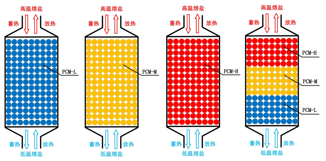
Figure 2 shows a schematic diagram of packed bed energy storage units with different arrangements of phase change materials. The first three types are single phase change packed bed energy storage units with different phase change temperatures, and the fourth type is a combination of the first three types. The temperature of the phase change materials decreases from top to bottom along the height of the tank, and the volume of each part of the phase change materials is the same. According to the arrangement of four phase change materials, observe the temperature changes of different energy storage systems during the energy storage process and compare their thermal performance indicators.