
1. Model assumptions
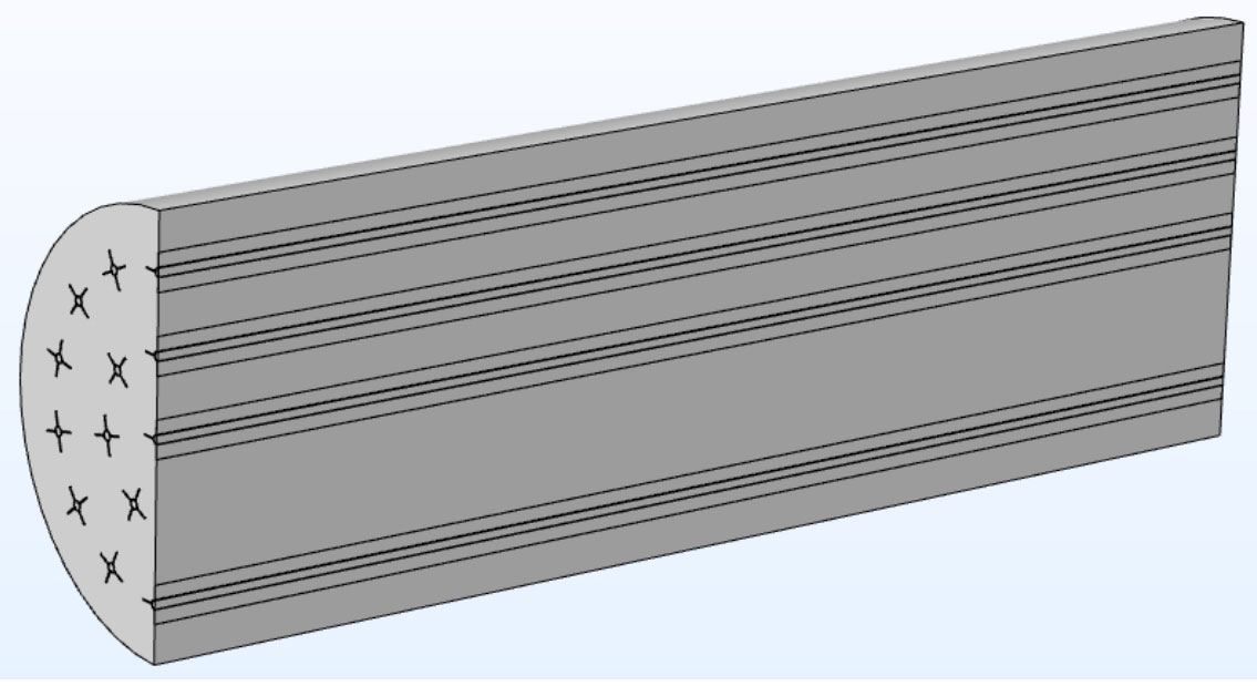
In order to better simulate the entire heat transfer process of concrete energy storage systems, a three-dimensional energy storage model was established for simulation and analysis. Due to the axisymmetric shape of the concrete energy storage system model, in order to reduce computational complexity, this article adopts the method of only calculating half of the model, considering the calculation range shown in Figure 1. Based on the structural characteristics and working principle of the introduced concrete energy storage unit, the following model assumptions are proposed:
(1) The concrete material in the energy storage system is homogeneous and isotropic;
(2) The peripheral insulation of the energy storage system module is good, and the heat loss to the environment can be ignored;
(3) The flow of heat transfer fluid is laminar;
(4) The heat transfer fluid is incompressible and is a Newtonian fluid;
(5) Fluid is fully developed in pipelines;
(6) The axial heat conduction and viscous dissipation of heat transfer fluids are ignored;
(7) The flow of air in the main pipeline is equivalent to passing through different fluid channels in the concrete energy storage system.
Calculate the flow velocity of fluid in the fluid channel of the energy storage system based on equations.
Among them, n represents the number of fluid channels in the concrete energy storage system, ??ℎ and ?? ube represent the cross-sectional area of the main pipeline and fluid channels respectively, ??ℎ represents the flow velocity of the fluid in the main pipeline, m/s, and ?? ube represents the flow velocity of the fluid in the fluid channel, m/s.
2. Heat transfer physical processes and control equations
Based on the above assumptions, a transient heat transfer mathematical model for concrete energy storage systems is established using fluid flow and solid heat transfer models. For the physical model of the concrete energy storage system mentioned above, in order to study its heat storage process, three physical processes: fluid flow, convective heat transfer, and heat conduction need to be simulated. Fluid flow heat transfer, energy transfer between fluid and concrete modules mainly follows the following equation:
For fluid flow processes, both the continuity equation and Navier Stokes equation are used, and the equation form is as follows:
Fluid transfers heat to the pipeline wall through convective heat transfer. Solving the convective heat transfer energy equation requires the velocity field calculated from the equation. The form of the convective heat transfer equation is as follows:
Among them, ρ, CP and k represent density, specific heat at constant pressure, and thermal conductivity, respectively. P is the uniform pressure of the fluid field, ? and μ They are the velocity vector of the heat transfer fluid and the dynamic viscosity coefficient. ?? ir and ?? respectively represent the temperature of the air fluid and the temperature of the concrete. Due to the inclusion of velocity in the energy equation and the influence of temperature and pressure on fluid properties, the conservation of mass, momentum, and energy in the energy storage system control equation is coupled.
3. Model validation
Compare the numerical simulation results of the above model with the research results of previous scholars to validate the model.
Two validation models are used here to verify the applicability of the concrete sensible heat energy storage system. The first validation model refers to Tamme et al.’s work. The physical model of the energy storage unit is a rectangular concrete energy storage unit, with thermal oil as the heat transfer fluid. There are parallel fluid pipelines inside the concrete unit, and the thermal oil heats the concrete medium for energy storage.
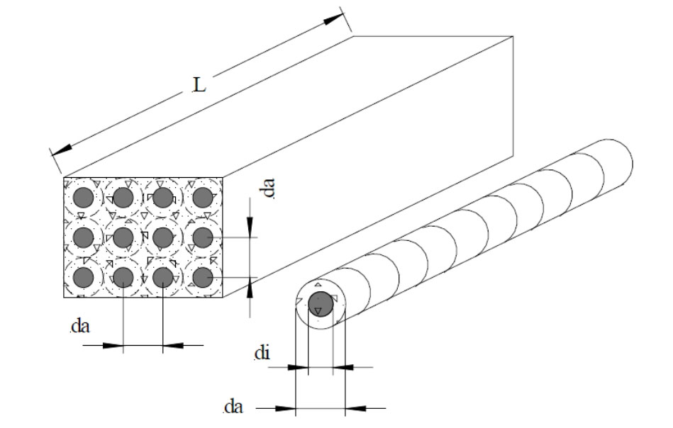
The distance da between the center points of two pipelines is 0.08m, and the inner diameter di of the fluid pipeline is 0.02m. The schematic diagram of the energy storage unit is shown in Figure 2. In order to verify the effectiveness of the mathematical model of concrete energy storage units in this article, the thermal storage time of energy storage units under different thermal conductivity coefficients was compared with the research results of Tamme et al. The thermal physical properties of the energy storage materials and fluids in the validation model, as well as the initial condition values of the model, are all derived from Tamme et al.’s research, as shown in Table. The boundary conditions of the model are: the fluid velocity at the inlet of the pipeline is 0.1m/s, the temperature of the fluid entering the inlet is constant at 390 ℃, and all other external surfaces of the model are adiabatic.
| Parameters | Size |
| Concrete density (kg/m ^ 3) | 2200 |
| Concrete specific heat (J/kg · K) | 1000 |
| Thermal conductivity of concrete (W/m · K) | 1.5/2/5 |
| Pipeline diameter di (m) | 0.02 |
| Pipeline spacing da (m) | 0,08 |
| Initial temperature (℃) | 350 |
| Fluid inlet temperature (℃) | 390 |
| Fluid density (kg/m ^ 3) | 761 |
| Fluid specific heat (J/kg · K) | 2800 |
| Fluid thermal conductivity (W/m · K) | 0.121 |
| Fluid dynamic viscosity coefficient (Ns/m ^ 2) | 0.02 |
| Duration (s) | 3600 |
The second validation model refers to the research work of Prasad and Muthukumar. Prasad and Muthukumar also used data from Table on the thermal properties of energy storage units and the heat storage process. They used numerical simulation methods and COMSOL Multiphysics 4.2 software to establish a three-dimensional mathematical model based on finite element analysis. Under different thermal conductivity coefficients, the average temperature of concrete energy storage units was observed over time.
The simulation results of the average temperature of the concrete energy storage unit in the first validation model over time are shown by the red dashed line in Figure 3 (a). From the comparison of the results in the figure, it can be seen that the numerical simulation results have good consistency with the research results of Tamme et al., with a maximum error of 2.8%. As the thermal conductivity increases, the concrete unit heats up faster and the time required to reach a relatively constant temperature is shorter. This is because the higher the thermal conductivity of concrete, the faster the energy storage unit absorbs heat and the shorter the heat storage time. When the thermal conductivity of concrete is 5 (W/m · K), the slope of the temperature curve at the beginning stage of the energy storage system is the highest, and the temperature rises the fastest. In the initial stage of heat storage, there are some small deviations between the simulation and actual results, mainly due to the neglect of axial heat conduction of the fluid in the simulation. Moreover, calculation errors and model assumptions can also lead to inconsistent results between the two.
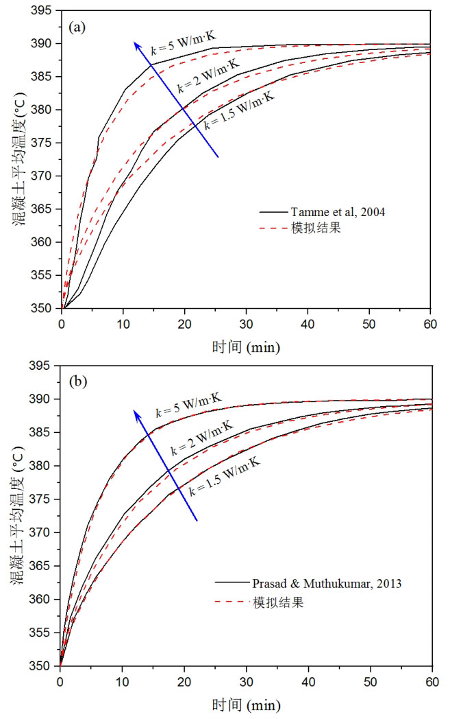
The trend curves of the second validation model and simulation results are shown in Figure 3 (b), which are basically consistent, indicating good effectiveness of the model. This is mainly because both are numerical simulation results under ideal conditions, without the influence of measurement errors and other factors.
Through the verification of the above two models, it can be concluded that the model used in this article has good applicability for simulating the energy storage process of concrete units, the calculation model is reliable, and can be used as an effective tool for simulating the thermal performance of concrete energy storage systems.