
1. Structure and operating principle of concrete energy storage system
The solid sensible heat energy storage system uses high-temperature concrete as the heat storage medium to store energy. Figure 1 shows a cross-sectional schematic diagram of a concrete energy storage system. From the figure, it can be seen that the energy storage system is mainly composed of concrete blocks, fluid heat transfer pipelines embedded in concrete, and mainstream pipelines.
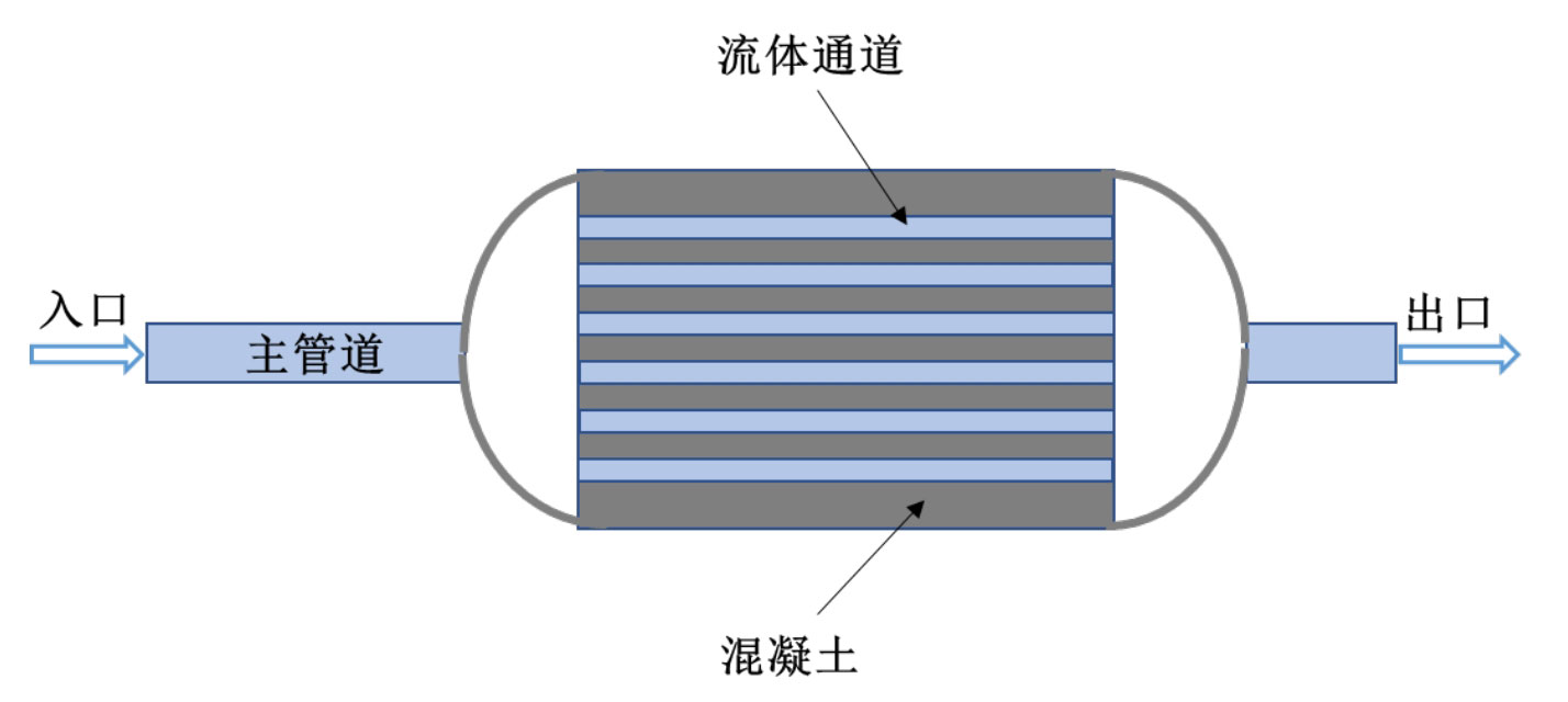
The concrete energy storage unit adopts a cylindrical geometric structure, with external insulation materials installed to reduce heat exchange with the outdoor environment during the energy storage process, thereby reducing heat loss. The two ends of the concrete energy storage unit are connected to the heat transfer fluid main pipeline, and many fluid flow pipelines are embedded inside to facilitate the rapid heat storage of concrete. At the same time, in order to further increase heat transfer efficiency, fins are arranged on the pipeline.
There are generally two types of sensible heat storage media, one is liquid sensible heat and the other is solid sensible heat. The most commonly used energy storage medium for high-temperature liquid sensible heat is molten salt, which is currently the most widely used energy storage system in photothermal power plants. Solid sensible heat materials are relatively abundant, commonly including sand, rock, cast ceramics, high-temperature concrete, cast iron, and cast steel. Compared to other solid energy storage materials, concrete is a more ideal energy storage medium for high-temperature sensible heat energy storage units.
This is because concrete is easy to obtain, the production process is simple, easy to operate, and the cost is relatively low, which has the possibility of large-scale application. At the same time, concrete has good durability and certain corrosion resistance under high temperature conditions, with a longer service life. The disadvantage is that the specific heat of concrete is relatively small, and the contact interface between the heat transfer pipeline and concrete can cause certain axial and radial tensile cracks due to different material thermal expansion and pressure.
Heat transfer fluids are also an important component of energy storage systems. The commonly used heat transfer fluids for high-temperature sensible heat storage include molten salt, thermal oil, air, and water/steam. Molten salt has a wide temperature range, high energy density, low viscosity, good fluidity, good thermal stability at high temperatures, low steam pressure, and relatively low cost. However, the melting point of molten salt is relatively high, and it needs to be heated to a liquid state before working. Low temperatures can easily solidify and cause pipeline blockage, resulting in relatively high operating and maintenance costs
Higher. At the same time, molten salt has strong corrosiveness at high temperatures, which can easily cause damage to pipelines. Heat transfer oil is generally liquid at room temperature, with good fluidity and weak corrosiveness. However, the thermal stability of heat transfer oil is poor, and the operating temperature generally does not exceed 400 ℃, with lower specific heat and relatively higher cost. The use pressure of the thermal oil system is above 1MPa, which is prone to safety issues such as fire and explosion, and has a short service life. Generally, it needs to be replaced every 3-5 years, resulting in high maintenance costs. As a rich resource, air has low viscosity, a wide working temperature range, less corrosion to containers, and low cost. However, the thermal conductivity of air is poor, the heat capacity per unit volume is small, and the work efficiency is low. The heat transfer efficiency of water/steam is relatively low, and the working pressure is relatively high, usually exceeding 10MPa. Moreover, in arid areas such as deserts, water is relatively scarce, and high-temperature applications are generally less common.
The concrete energy storage unit utilizes heat from the heat transfer fluid for heat storage. During the thermal storage cycle, the heat transfer fluid is first heated to a predetermined temperature by the heat collection device. Then, under the action of the circulation pump, the high-temperature fluid flows into the energy storage unit from the main pipeline, and undergoes heat exchange with the concrete, causing the temperature of the concrete to rise for thermal storage. After heat exchange, the fluid temperature decreases, and the cold fluid flows out of the energy storage unit. After being heated by the heating device, it can be recycled. The thermal storage efficiency of concrete energy storage units is closely related to geometric structure, operating parameters, and selection of heat transfer fluids.
2. Filling bed energy storage unit system and operating principle
Dual tank molten salt energy storage is currently the most widely used commercial energy storage method, but its energy storage cost is also relatively high. In order to reduce investment costs, single tank energy storage technology is receiving increasing attention. The schematic diagram of a single tank filled bed energy storage system is shown in Figure 2. The packed bed energy storage system includes a vertically installed cylindrical tank with two outlets, one at the top and one at the bottom, respectively used for the passage of heat transfer fluids during the heat storage and release processes. The tank is filled with encapsulated phase change spheres of the same shape and size for energy storage. The heat transfer fluid can flow in the gaps of these spherical phase change materials and exchange heat with them. A splitter is installed at the inlet and outlet of the energy storage unit, which allows the fluid to pass through the packing area more evenly. The outer surface of the tank is wrapped with insulation materials to reduce heat dissipation towards the outside.
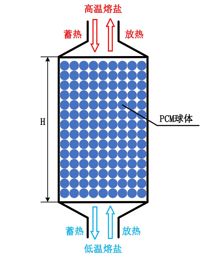
The principle of a single tank molten salt energy storage unit is to utilize the difference in density of molten salt at different temperatures, which leads to natural convection of molten salt in the tank body. This results in a natural layering phenomenon with a large temperature gradient in the center of the tank body, which is a “inclined temperature layer”. Above the inclined temperature layer is the high-temperature molten salt area, and below is the low-temperature molten salt area. As the heat storage and release process progresses, the inclined temperature layer will move up and down, and the output fluid thermal energy will also remain stable for a long time. When the inclined temperature layer reaches the top or bottom of the tank, the temperature of the flowing fluid will undergo significant changes. In order to maintain a relatively stable outflow temperature, in a single tank packed bed energy storage system, it is necessary to reasonably control the working parameters such as fluid flow rate based on the size and porosity of the solid energy storage medium in the tank.
The volume of a single tank filled bed energy storage unit is relatively small, but in a smaller volume, the heat transfer surface area of the spherical energy storage medium is larger. There is irregular flow of heat transfer fluid in the gaps between the spherical energy storage medium in the tank, and heat exchange occurs between the fluid and the energy storage medium. The working process of the packed bed energy storage unit includes two processes: heat storage and heat release. During the heat storage process, the hot fluid flows in from the top of the tank, forms a uniform flow through a splitter, and then exchanges heat with the phase change energy storage medium in the tank. The temperature of the energy storage medium increases, and the inclined temperature layer moves towards the bottom of the tank. Then, the cold fluid flows out from the bottom outlet.
As heat storage progresses, the temperature of the fluid flowing out from the bottom increases. When the temperature of the heat transfer fluid reaches the set heat storage cut-off temperature, the heat storage process ends. During the heat release process of the energy storage system, low-temperature fluid flows in from the inlet at the bottom of the tank and forms a uniform flow state under the action of a splitter. After exchanging heat with the high-temperature energy storage medium, the temperature rises. At the same time, the inclined temperature layer moves towards the top of the tank. As the heat release process continues, the temperature of the fluid flowing out increases. When the set temperature is reached, the heat release process ends. The heat transfer rate is a function of the temperature difference between the fluid and the energy storage material, and as the temperature difference between them decreases, the heat transfer rate will gradually decrease.