
This paper introduces the structure of a distributed balanced charging system for series energy storage power sources, and provides three working modes of the distributed balanced charging system for series energy storage power sources. The principles of the bidirectional DC converter’s voltage rise and fall operation and the working principles of the four cell equalizer are analyzed respectively. A model was established for the four cell equalizer, and corresponding formulas for balancing current and balancing efficiency were derived. Finally, the feasibility of the three modes of charging balance, intra group balance, and cross group balance in the distributed balanced charging system with series energy storage power sources was verified through simulation, as well as the correctness of the four cell equalizer modeling.
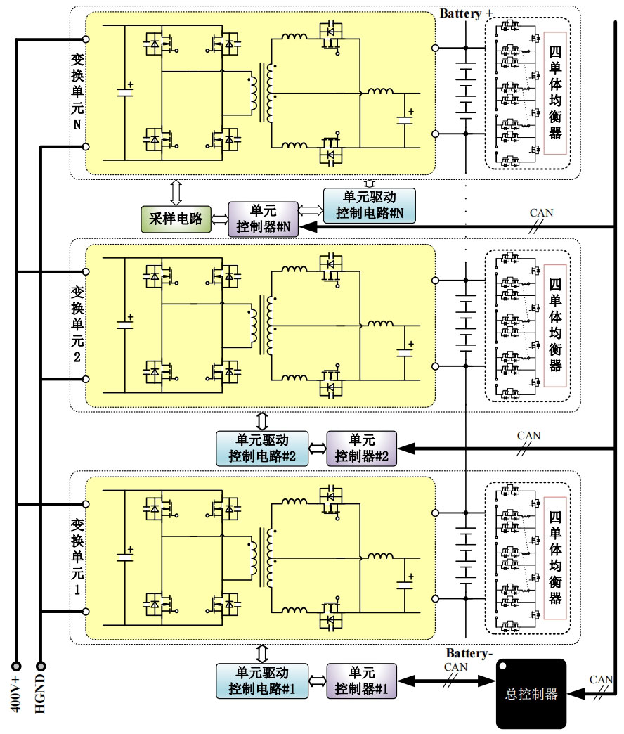
The distributed balanced charging block diagram of the proposed series energy storage power supply is shown in Figure 1. The system consists of N balanced charging modules connected in parallel with input and output in series. Each balanced charging module is regarded as a transformation unit of the distributed balanced charging of the series energy storage power supply. The transformation unit is composed of a bidirectional DC converter and a four cell equalizer combination. At the same time, each transformation unit is equipped with an analog front-end circuit The driving circuit and unit controller are finally transmitted with specific instructions through CAN bus communication by a main controller to control the operation of each transformation unit. The entire structure can be seen as a distributed balanced charging system consisting of two layers of series connected energy storage power sources composed of multiple transformation units. Choose the full bridge push-pull topology as the main topology of the bidirectional DC converter. The input end of each bidirectional DC converter, i.e. the input side of each transformation unit, is parallel connected to a 400 ± 5% V DC bus, and N transformation units form a distributed parallel relationship; The output side of the bidirectional DC converter is connected to four series connected battery packs with an equalizer, and N battery packs are connected end-to-end to form a long chain series battery pack, which serves as the power source for external output. When all bidirectional DC converters operate in step-down mode, the control method of primary side phase-shifting full bridge and secondary side synchronous rectification is adopted to charge each battery group, and the four cell equalizer can be used to achieve the balancing function of the charging process; When the bidirectional DC converter partially operates in boost mode and partially operates in buck mode, the distributed balanced charging system with series energy storage power sources enters a cross group balancing state between battery groups. It can also be paired with a four cell equalizer to accelerate the balancing progress, and the balancing speed of cross group balancing is much greater than that of the four cell equalizer. Among them, when the bidirectional DC converter operates in boost mode, it is actually a push-pull operation mode, which adopts a control method based on voltage natural clamping. By using specific control of the high-voltage side MOSFET to clamp the low-voltage side MOSFET, it can achieve zero current turn off of the low-voltage side MOSFET and zero voltage turn on of the high-voltage side MOSFET. It can also suppress voltage spikes generated on the low-voltage side and improve transmission efficiency; When the bidirectional DC converter is not working, each battery group can perform intra group balancing to prioritize local balancing, and then coordinate with other balancing mode actions to complete the balancing of the entire long chain battery group, which can efficiently and quickly eliminate the inconsistency of the long chain battery group.
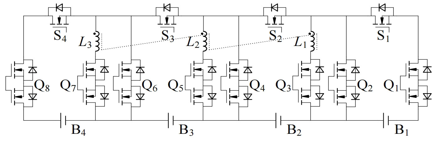
The four cell equalizer, as shown in Figure 2, adopts a coupled inductor type multipath balancing topology, which consists of four high-frequency switches, eight bidirectional switches, and three coupled inductors. It can achieve direct balancing of any two cell units within the battery group through buck boost mode and flyback mode. In the operation of the distributed balanced charging system of the entire series energy storage power supply, it can work in any of the three modes at any time. As long as there is imbalance among the battery cells in the battery group, the four cell equalizer will start working.
| Charging system parameters | Rated value or parameter range |
| DC bus voltage range | 400 ± 5% V |
| Converter switching frequency (bidirectional) | 100kHz |
| Range of forward output voltage (reverse input voltage) | 11-14.6V |
| Rated power for charging | 500W |
| Rated power for discharging | 120W |
A bidirectional DC converter can achieve bidirectional transmission of electrical energy, which can charge the battery pack and ensure voltage balance in the charging state of the circuit, as well as feedback the energy of the overcharged battery pack to the over discharged battery pack in the discharging state. The distributed balanced charging system of the entire series energy storage power supply controls the switching status of the MOS transistors inside the bidirectional DC converter and the four cell equalizer through two sets of subroutines, thereby constructing different charging, discharging, and balancing paths. In actual use, real-time control is combined with different functional requirements and battery balance status to meet the balance requirements under complex imbalances. The main parameters of the distributed balanced charging system with series energy storage power sources are shown in the table.