
Solar power plants are equipped with compensation devices with large capacity, which accounts for about 25% of the total system capacity. This can maintain a constant system voltage and ensure the balance of reactive power. The main drawbacks of this measure are high cost, power loss, and the generation of high-order harmonic components. This is because with the significant increase in power station capacity, the capacity of its compensation equipment also increases, which will result in a huge investment in reactive power compensation. When solar power plants are connected to the grid, the timeliness of reactive power compensation is not particularly high. Therefore, in order to reduce the cost investment caused by reactive power compensation, the reactive power regulation ability of the inverter device itself is usually used to compensate for the current reactive power demand of the power plant. This can control power loss, It can also ensure the economic efficiency of reactive power compensation.
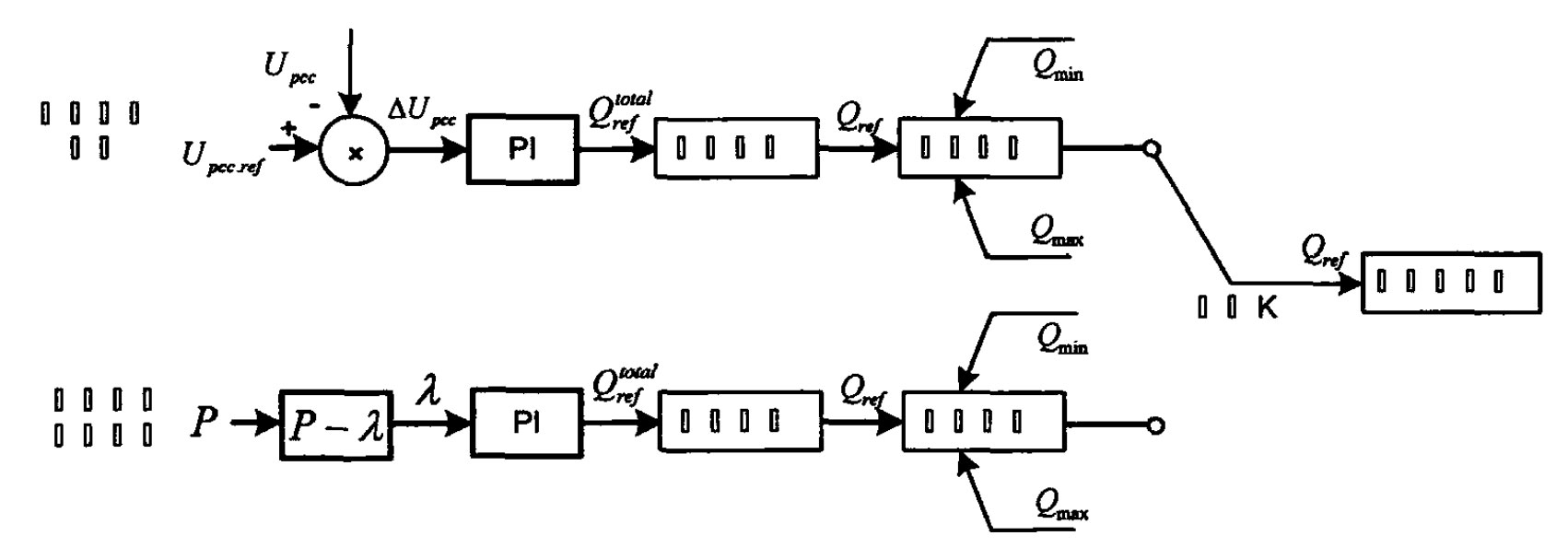
At present, for the control of solar inverters, the classic double closed-loop control structure is usually used. The voltage outer loop control is used to determine the reference value of the current, while the current inner loop control is used to achieve fast tracking of the current reference value. From Figure, it can be seen that its control strategy can be composed of two parts, namely adjusting voltage mode and system reactive power compensation mode.
When faults such as power grid fluctuations occur, which can cause certain changes in the voltage of the power grid, it operates in an adjusted voltage mode. Under normal operating conditions, photovoltaic power plants need to compensate for the reactive power required by the system and operate in the system reactive power compensation mode, thus constructing P- λ Power factor curve. W can be divided into the following steps for construction:
(1) Based on the criteria under normal operating conditions, construct and simulate the model and perform power flow calculations.
(2) Calculate the reactive power demand of the power station under normal operation, and thus obtain the power factor P under this operating condition- λ Curve.
(3) The power factor P obtained under these operating conditions- λ Make slight adjustments to the curve.
The reactive power control strategy shown in Figure 1 aims to compensate for the required reactive power of the system when the fluctuation of the access point Upcc is not significant. The reactive power adjustment reference command of a single solar inverter after reactive power allocation is used as the final target for controlling the output reactive power of the solar inverter through real-time reactive power limiting loop; When the voltage Upcc fluctuation at the access point is relatively large, it is used as the final reactive power target for the control output of the solar inverter after reactive power allocation and reactive power limiting loop.
To compensate for the reactive power required by the system, a solar inverter reactive power control strategy is constructed for the operation of photovoltaic power plants. The P-input operation relationship curve applicable to photovoltaic power plants is obtained with the goal of compensating for the reactive power required by the power grid. Taking the actual operation of a photovoltaic power station in Qinghai Province as an example, the reactive power regulation ability of the solar inverter itself can replace the reactive power compensation device, saving investment in the photovoltaic power station. The annual energy-saving benefit brought by reducing line losses is preliminarily calculated to be 25500 yuan.