
| Parameters | Simulation value |
| Rated DC voltage Vdc | ± 10kV |
| Rated AC voltage Uac | 10kV |
| AC rated power Pac | 6MW |
| Number of bridge arm submodules N | 30 |
| Network side inductance L | 8mH |
| Bridge arm inductance Larm | 5mH |
| Switching frequency fs | 5kHz |
| Rated voltage of battery pack vbat | 800V |
| Battery internal resistance Rb | 0.1 Ω |
To verify the effectiveness of the proposed modular multilevel converter-battery energy storage system charge throughput suppression strategy, a simulation model of modular multilevel converter-battery energy storage system was built in MATLAB/Simulink, and its system parameters are shown in Table 1. The DC voltage of the system is ± 10kV, the effective value of the rated AC line voltage is 10kV, and the modulation ratio m at the rated voltage is 0.8165. modular multilevel converter-battery energy storage system can operate in either rectification or inversion states, while batteries can operate in charging or discharging states. The suppression effect of charge throughput in battery energy storage systems varies under different operating states. Therefore, this article uses the CCSC method as a comparison to verify the effectiveness of the charge throughput suppression strategy under the four typical operating conditions in Table 2.
| Working conditions | MMC-BESS | Battery | AC power | DC power | K | Simulation result |
| Simulation condition 1 | Inversion | Charging | 5MW | 6MW | 0.2 | Figure 1 |
| Simulation condition 2 | Inversion | Discharge | 5MW | 4MW | -0.2 | Figure 2 |
| Simulation condition 3 | Rectification | Charging | -5MW | -4MW | -0.2 | Figure 3 |
| Simulation condition 4 | Rectification | Discharge | -5MW | -6MW | 0.2 | Figure 4 |
1. Simulation results
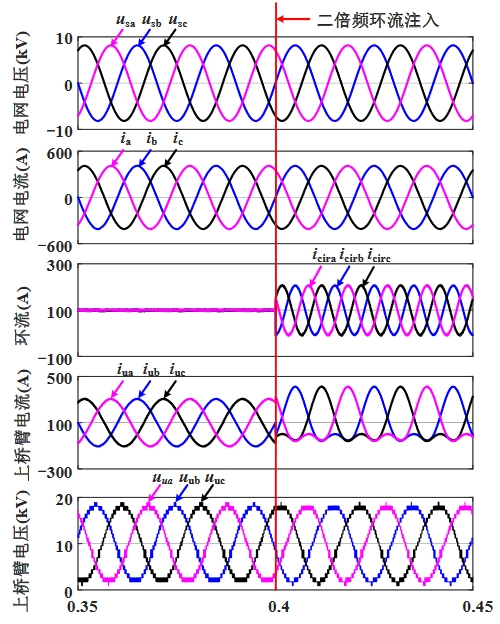
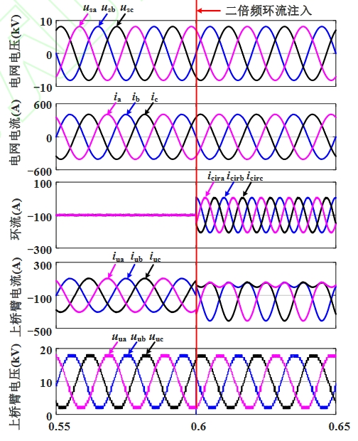
The comparative simulation results of the four typical working conditions mentioned above are shown in Figures 1 and 4, respectively. The traditional CCSC control method was used before the red line moment, and the proposed charge throughput suppression strategy was used to inject the optimal second harmonic circulation at the corresponding time of the red line.
Simulation condition one: The simulation results are shown in Figure 1, with an AC power of 5MW and a DC power of 6MW. The modular multilevel converter-battery energy storage system operates under the inverter condition, with the battery in a charging state, a battery power of 1MW, and an AC current amplitude of approximately 413.6A. 0.35s-0.4s, without suppressing charge throughput, modular multilevel converter-battery energy storage system adopts CCSC strategy to suppress circulating current, with a DC component of approximately 100A; At 0.4s, inject amplitude coefficient λ It is a 0.26 second harmonic circulation with an amplitude of approximately 107.5A.
Simulation condition 2: The simulation results are shown in Figure 2, with an AC power of 5MW and a DC power of 4MW. The modular multilevel converter-battery energy storage system operates under the inverter condition, and the battery is in a discharge state. The battery power is -1MW, and the AC current amplitude is about 413.6A. 0.55s-0.6s, without suppressing charge throughput, modular multilevel converter-battery energy storage system adopts CCSC strategy to suppress circulation, with a DC component of approximately 80A in circulation; At 0.6s, inject amplitude coefficient λ The amplitude of the 0.34 second harmonic circulation is approximately 140.6A.
Simulation condition three: The simulation results are shown in Figure 3, with an AC power of -5MW and a DC power of -4MW. The modular multilevel converter-battery energy storage system operates under rectification condition, with the battery in a charging state, a battery power of 1MW, and an AC current amplitude of approximately 413.6A. 0.35s-0.4s, without suppressing charge throughput, modular multilevel converter-battery energy storage system adopts CCSC strategy to suppress circulating current, with a DC component of approximately -80A; At 0.4s, inject amplitude coefficient λ The amplitude of the 0.34 second harmonic circulation is approximately 140.6A.

Simulation condition four: The simulation results are shown in Figure 4, with an AC power of -5MW and a DC power of -6MW. The modular multilevel converter-battery energy storage system operates under rectification conditions, and the battery is in a discharge state. The battery power is -1MW, and the AC current amplitude is about 413.6A. 0.55s-0.6s, without suppressing charge throughput, modular multilevel converter-battery energy storage system adopts CCSC strategy to suppress circulating current, with a DC component of approximately -100A; At 0.6s, inject amplitude coefficient λ It is a 0.26 second harmonic circulation with an amplitude of approximately 107.5A.

2. Analysis of simulation results
The comparison of simulation results before and after charge throughput suppression under four operating conditions is shown in Table 3.
| Operating conditions | Control strategy | Charge throughput/C | Inhibition rate |
| Simulation condition 1 | Traditional methods | 22.03 | 37.58% |
| Simulation condition 1 | Proposed method | 13.77 | 37.58% |
| Simulation condition 2 | Traditional methods | 23.75 | 24.51% |
| Simulation condition 2 | Proposed method | 17.93 | 24.51% |
| Simulation condition 3 | Traditional methods | 23.82 | 24.22% |
| Simulation condition 3 | Proposed method | 18.05 | 24.22% |
| Simulation condition 4 | Traditional methods | 22.27 | 37.09% |
| Simulation condition 4 | Proposed method | 14.01 | 37.09% |
Under the above four simulation conditions, the proposed methods can effectively suppress the charge throughput of modular multilevel converter-battery energy storage system. According to the results of simulation conditions one and two, it can be concluded that when the battery power is constant, the charge throughput generated by modular multilevel converter-battery energy storage system is smaller when k>0 than when k<0, and the proposed method has a higher suppression rate; According to the results of simulation conditions one and four, it can be concluded that when the modulation ratio and AC power are constant, the charge throughput and suppression rate of modular multilevel converter-battery energy storage system are only related to k, and are independent of the direction of AC power flow.