
The grid connected system Uref is set to 500V, and a three-phase 220V 50Hz voltage source is used to simulate the three-phase power grid. The DC side capacitance value is 850 μ F. The SVPWM module Ts is set to 0.00005, and the output of the solar inverter is connected to the power grid through the LCL capacitor branch series resistor passive damping filter.
The system structure includes the main circuit, PI control module, PR control module, and SVPWM control module. The solar inverter circuit adopts a three-phase full bridge solar inverter, the current inner loop uses a PR regulator, and the voltage outer loop uses a PI regulator. The results are transmitted to the SVPWM module to generate a driving signal to drive the solar inverter to work and achieve unit power factor grid connected operation. The system structure is shown in Figure 1.
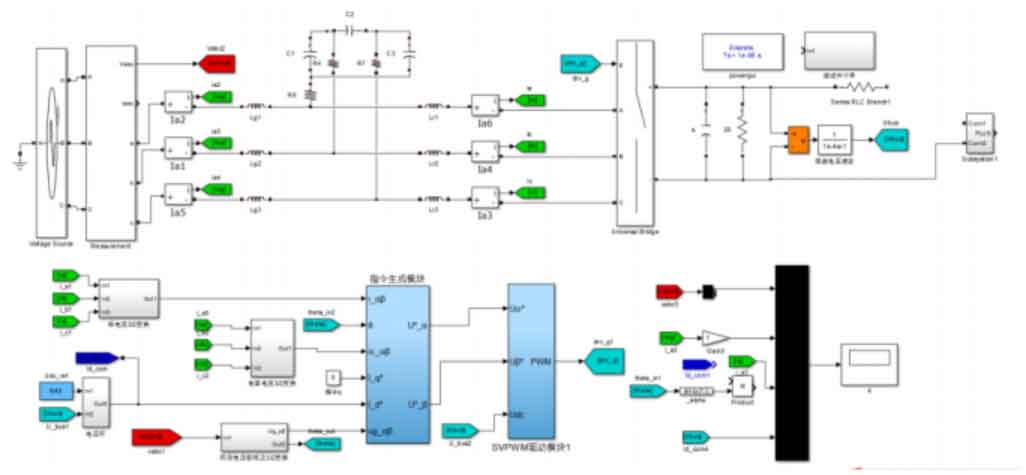
The voltage source in the figure simulates the voltage of an infinite power grid system. Lg1-3, Lr1-3, and C form the LCL filter of the solar inverter, and the output currents ia, ib, and ic of the solar inverter are measured. The grid side currents iag, ibg, icg, and capacitor currents ica, icb, and icc are converted into current 3/2 and input into the command generation module for active damping. The DC side voltage Ubus is collected and passed through the voltage outer loop PI regulator, along with the active component instruction Id_ Com jointly inputs active current component I_ D *, assuming the system operates under unit power factor conditions, therefore I_ The input of q * is 0, and the three-phase voltage Uabcs on the grid side is input to ug through a voltage phase-locked loop and a 3/2 conversion_ ΪΫ, Generate U through instruction generation module_ Ϊ And U_ Ϋ, Simultaneously inputting the DC side voltage into the SVPWM drive module to generate the SVPWM control wave drv of the solar inverter_ After g, input it into the solar inverter module universal bridge, and use oscilloscope 4 to collect the grid side voltage Uabcs, phase a current Ia2, and current active component input value Id_ Display com and DC side voltage Ubus. Due to the significant increase in system structure, if PowerGUI continues to operate in continuous mode, although the simulation accuracy can be guaranteed, the simulation time will be greatly increased. Therefore, the discrete mode is adopted and Ts=e-06s is set.
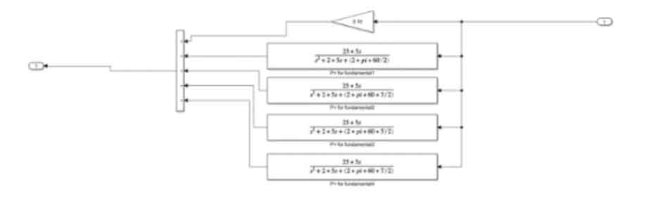
The current inner loop is controlled by a PR regulator, and the system PR regulator parameters are shown in Figure 2.
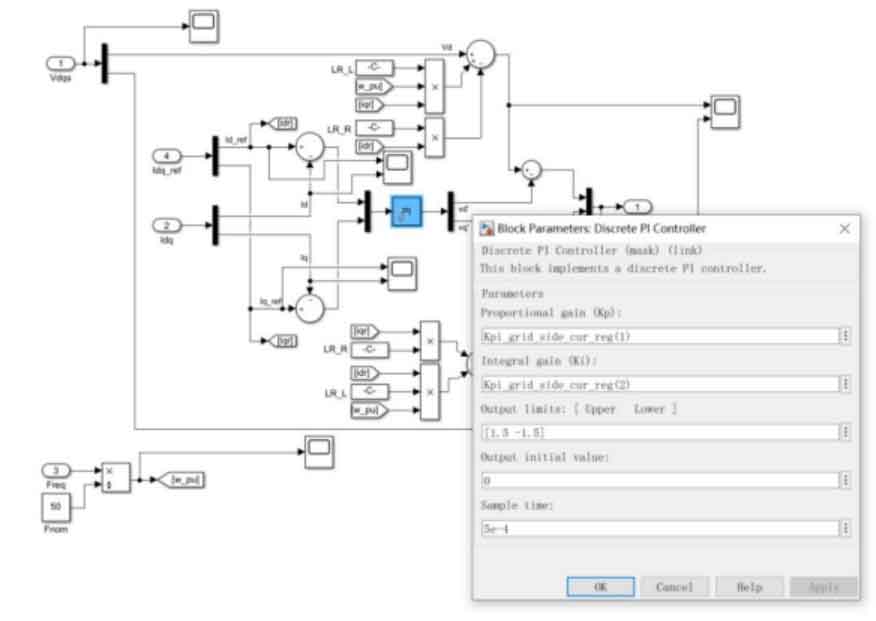
The voltage outer loop is controlled by a PI regulator, and the system PI regulator parameters are shown in Figure 3.
The simulation waveform is shown in Figure 4.
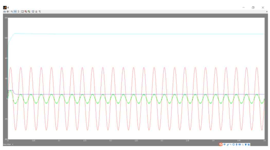
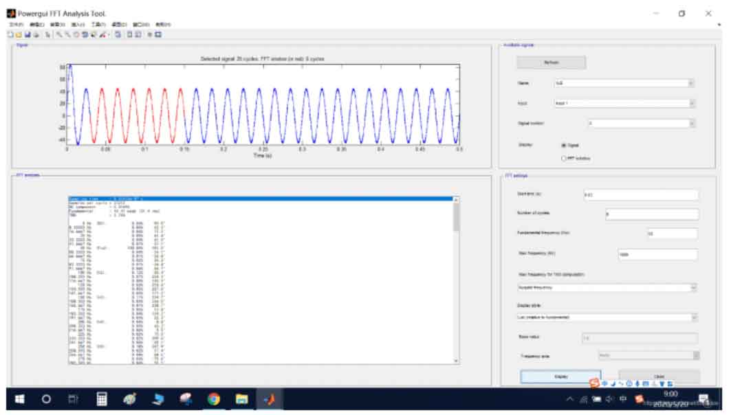
The red color in the figure represents the A-phase voltage, the blue color represents the DC bus voltage, the green color represents the A-phase current, and the blue color represents the active component input of the current. The solar inverter operates at a unit power factor state, and the current harmonic content is shown in Figure 5.
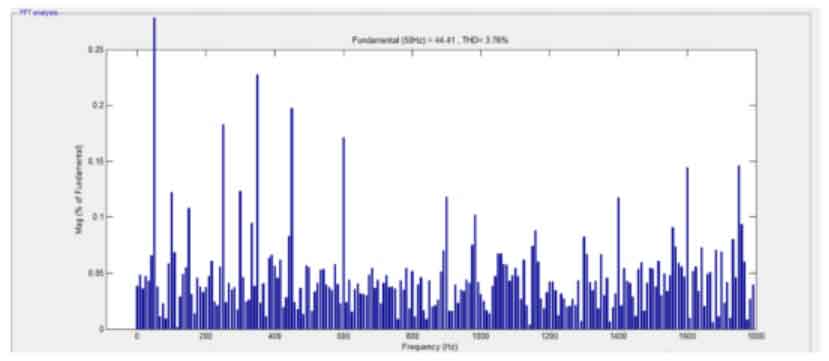
By using FFT tools to analyze the harmonic content of the output current iga of solar inverters, 25 cycles were collected, and 6 cycles of the stable stage were adopted for analysis. The fundamental frequency was set to 50Hz, and the maximum frequency was analyzed up to 90 harmonics. The total harmonic content THD of each harmonic added up was 3.76%, which meets the requirement of harmonic content<5% for photovoltaic system grid connection technology (GB/T 19939-2005). The parameters and analysis results of the FTT analysis tool are shown in Figure 6.
Based on the above simulation results, the grid connected system can transmit active and reactive power to the grid during normal operation, and can also perform current harmonic detection, meeting the grid connection requirements.
Grid connected photovoltaic power generation is the mainstream development direction of photovoltaic power generation. This paper conducts in-depth analysis and research on photovoltaic power generation systems, and the main research contents are as follows:
(1) This article analyzes and introduces the working principle of photovoltaic cells and establishes their mathematical models. Based on the established mathematical model, simulation work of photovoltaic module characteristic curves in different external environments was carried out in Simulink, providing a simulation basis for MPPT control of boost circuits.
(2) Analyzed the characteristics of various structures and the control methods of solar inverters based on the structure of photovoltaic grid connected systems and solar grid connected inverters; By comparing the advantages and disadvantages of various structures, a two-stage basic boost multi-stage non isolated solar grid connected inverter was adopted as the main circuit structure of the solar grid connected inverter.
(3) For the control strategy of solar grid inverters, the control principles and advantages and disadvantages of four commonly used control strategies, VOC, VFOC, V-DPC, and VF-DPC, were analyzed. The improved VF-DPC control strategy, current inner loop PR regulator control, voltage outer loop PI regulator control, photovoltaic component DC voltage feedforward strategy, and SVPWM modulation control strategy were determined.
(4) The principle of LCL filter was analyzed, and the resonance problem of LCL was solved through active and passive damping methods. The circuit parameters of the LCL filter with capacitor branch series resistance were determined through parameter calculation, and a simulation model was constructed and simulated.
(5) An analysis and comparison were conducted on the MPPT control method of the front-end boost circuit, and an improved control method was proposed for the oscillation and misjudgment problems of the disturbance observation method and the conductance increment method. Simulation models of the boost circuit based on the disturbance observation method and the conductance increment method MPPT were built, respectively. After comparing the simulation results, it was determined to use the boost circuit controlled by the conductance increment method MPPT as the front-end part of the solar grid connected inverter.
(6) A simulation model of the grid connected system was built, and after simulation, it was shown that the solar grid connected inverter has good performance in all aspects and meets the system requirements for grid connected power generation.
The simulation conditions for photovoltaic grid connected systems are all based on ideal conditions. Compared to other problems such as unstable power electronic components in solar grid connected inverters and intermittent photovoltaic power generation systems in reality, further solutions are needed. The shortcomings of this article are as follows:
(1) The parameter selection of the front-end boost circuit, especially the parameter selection of power electronic components, has a significant impact on conversion efficiency, maximum power point tracking accuracy, etc. It should be combined with the actual characteristics of power electronic components for more precise simulation calculations.
(2) When the system is connected to the grid, it should be considered to add a synchronization device to the solar grid inverter.
(3) After a power loss on the grid side, the system switches to island operation, and corresponding fast switching control strategies should be adopted to reduce voltage and frequency fluctuations, and can operate independently for a stable and long-term period.