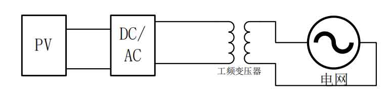
Isolation type solar grid connected inverters can be divided into power frequency isolation type and high-frequency isolation type based on the operating frequency of the transformer. The structure of power frequency isolation type solar grid connected inverters is shown in Figure 1.
The power frequency isolated solar grid connected inverter has the following advantages:
(1) It does not involve any frequency changes other than power frequency, has a simple circuit structure, and high system operation reliability.
(2) Due to the presence of isolation transformers, there is no issue of direct current entering the power grid, which improves the safety of system operation.
(3) The power frequency transformer is not only responsible for isolation, but also for voltage matching function, reducing the requirements for photovoltaic arrays.
However, power frequency solar grid connected inverters also have the following drawbacks:
(1) Power frequency transformers have a large volume and mass, resulting in reduced noise and inverter efficiency.
(2) Due to the high proportion of power frequency transformers, the cost of power generation has increased.
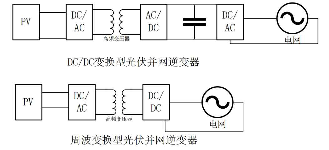
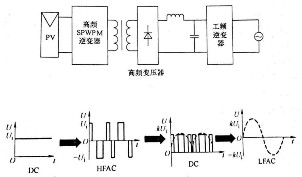
According to the empirical formula E=4.44fN in electrical engineering Φ It can be seen that in order to overcome the various drawbacks of power frequency isolated solar inverters, while keeping the number of turns and magnetic flux constant, the induced electromotive force can be significantly increased with the increase of working frequency. Therefore, a high-frequency isolated solar inverter solution has been derived. Compared with power frequency isolated solar inverters, high-frequency isolated solar inverters have advantages such as small size, light weight, and low power generation cost. High frequency isolated solar grid connected inverters can be mainly divided into two categories: DC/DC conversion type and cycle conversion type, and their structures are shown in Figure 2.
Power frequency isolated solar grid connected inverters are also classified into various types according to the requirements of usage conditions, as shown in the table.
| Single-phase structure | Single phase full bridge type |
| Single-phase structure | Single phase half bridge type |
| Three-phase structure | Two level three-phase full bridge type |
| Three-phase structure | Three level three-phase full bridge type |
| Three-phase structure | Three phase multiple structure |
The single-phase structure is limited by only one phase of AC, so the single-phase structure of solar grid connected inverters mostly have several kW power levels, and their DC side requires a DC voltage generally not higher than 600V, and the working efficiency is also less than 96%; The three-phase structure is suitable for hundreds of kW level photovoltaic inverter fields due to the three-phase AC power on the AC side. The two-level three-phase full bridge parallel solar inverter operates at a voltage of 450-820V, with an efficiency of ≈ 97%. The three-level three-phase global solar inverter operates at a voltage of 600-1000V, with an efficiency of ≈ 98%. The three-phase multiple structure is similar to the master-slave structure, It will switch the operation status of the solar inverter according to the actual situation and always maintain efficient inverter, with the same working voltage and efficiency as the two-level three-phase full bridge solar inverter.
There are two control methods for high-frequency isolated solar grid connected inverters:
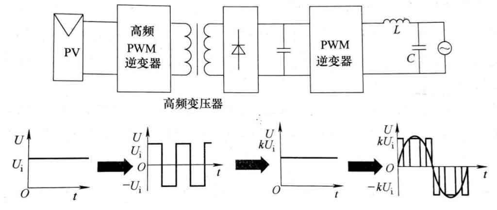
(1) The front-end high-frequency solar inverter generates a D=50% conversion into a high-frequency two electric square wave voltage, which is then transformed into a power frequency voltage through a high-frequency transformer and fed into the power grid through the back-end low-frequency solar inverter. Its operating mode is shown in Figure 3.
(2) The front stage high frequency solar inverter generates three-level high frequency SPWPM wave after being modulated by SPWPM, and then it is rectified to DC Mantou wave by the high frequency solar inverter and rectifier bridge. After being transformed into power frequency voltage by the rear stage power frequency solar inverter, it is fed into the power grid. Its working mode is shown in Figure 4.
Similarly, there are also these two operating modes in the high-frequency link solar grid connected inverter with cycle conversion. The second working mode adopts SPWPM modulation, and there is no DC link during energy conversion. When using bidirectional switches, bidirectional power flow can be achieved, providing the possibility for the implementation of wind solar complementary energy storage systems.
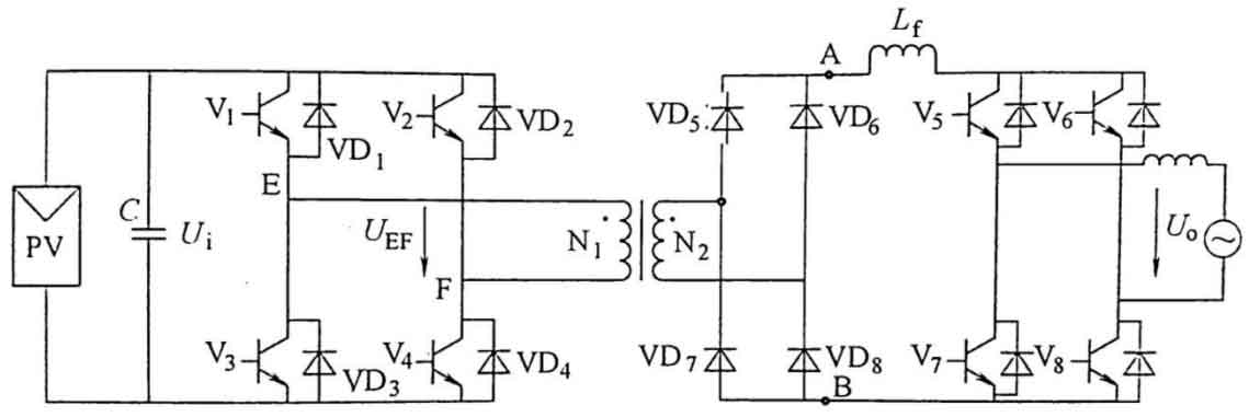
The front-end high-frequency solar inverters of DC/DC conversion type grid connected solar inverters can be in the forms of full bridge, half bridge, push-pull, etc. The back-end power frequency solar inverters can be in the forms of full bridge, half bridge, etc. The front-end is determined based on the input DC voltage. The full bridge and half bridge are suitable for situations with high input voltage, while the push-pull is suitable for situations with low input voltage, The commonly used DC/DC conversion high-frequency link solar grid connected inverters are mostly front and rear stage full bridge structures, and their circuit topology is shown in Figure 5.
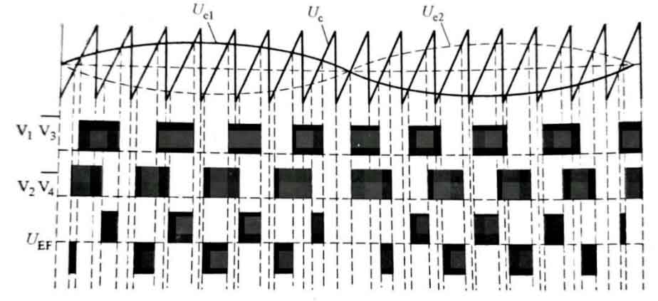
When the circuit in the figure adopts working mode 2, the front and rear stage controls can be relatively independent, and the control logic is simple. The front stage high-frequency solar inverter can display zero voltage on (ZVS); The rear stage solar inverter can achieve zero voltage on and zero current off (ZVZCS) with low switching stress. The switch timing diagram is shown in Figure 6.
Similarly, the front stage of the cycle conversion type solar grid connected inverter can also adopt full bridge, half bridge, push-pull and other forms. The rear stage cycle converter has full wave and full bridge circuits, and the use of the rear stage is determined based on the output voltage:
(1) When the output voltage level is low, in order to reduce the cost of power generation, a full wave circuit structure is generally adopted. The full wave circuit is suitable for low output voltage situations, and it uses fewer power switching components. However, due to the need to withstand half wave voltage, the switching stress is relatively high, and the transformer winding utilization rate is only 50%. However, because the power is generally low, it is also a commonly used circuit structure.
(2) When the output voltage level is high, considering the manufacturing cost of power switch components, full bridge circuits can significantly reduce switch stress, and the utilization rate of transformer windings is also high. However, this brings about the problem of using more power switches.
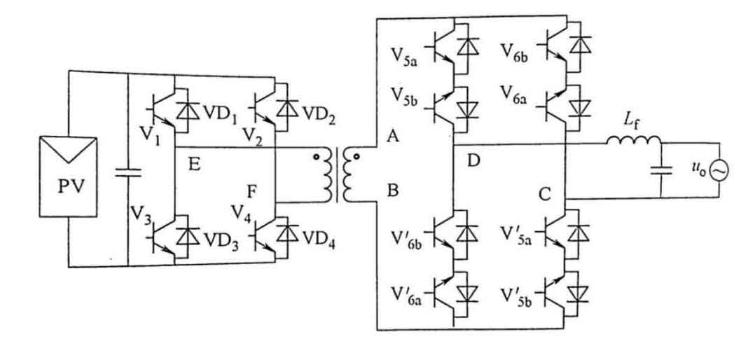
This article still takes the full bridge cycle conversion high-frequency link solar grid connected inverter as an example, and its circuit topology is shown in Figure 7.
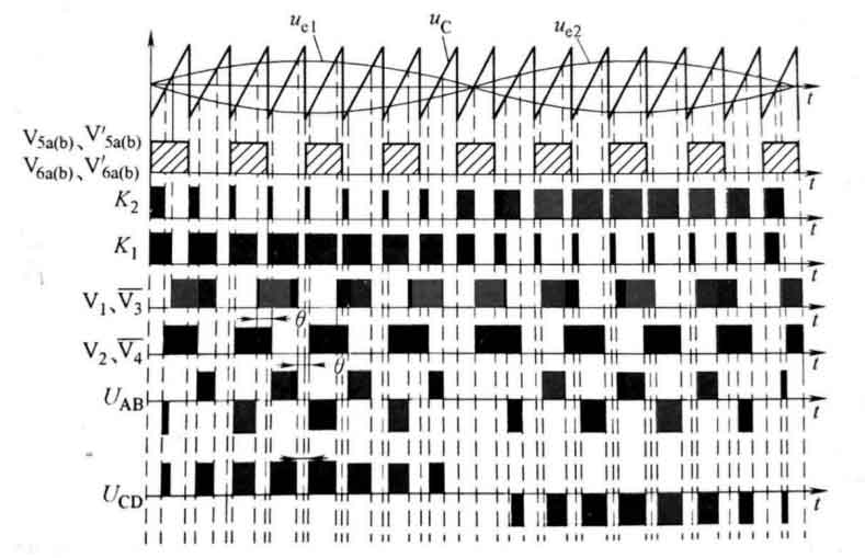
When working in mode 2, the front and rear stages need to be synchronously controlled. Through phase-shifting control, the front stage high-frequency solar inverters V1 and V3 can achieve zero voltage turn-on and turnoff, while V2 and V4 are fully voltage turn-on; When the UAB is zero, the subsequent cycle converter conducts a circulating current, which can achieve zero voltage turn-on and turn off, and can also make the output filtering inductance ILf continuous. The control principle and switch timing are shown in Figures 8 and 9.