For the control method of three-phase solar grid connected inverters, it is the core of the entire control process. Common methods include voltage oriented and virtual flux oriented control, current closed-loop vector control, and power closed-loop direct power control. According to open-loop or closed-loop, they can be divided into indirect current control and direct current control, etc. Among the current control algorithms, the most important and commonly used is current control technology.
Current control technology can be divided into two types: direct and indirect. Indirect current control is commonly used in situations where fast switching is required. It is an open-loop control method that cannot provide immediate feedback, and its response speed is relatively slow. At the same time, it cannot guarantee the quality of the output waveform well, which can cause certain disturbances to the normal operation of the power grid. So, currently, the current control of grid connected technology usually uses direct current control, adding an instant feedback loop to form closed-loop control, which makes the entire system more stable, output waveform quality higher, reduces the disturbance impact on the power grid, and thus improves the robustness of the system.
The commonly used methods for achieving direct control of current include classical PI regulation, proportional resonance control, repetitive control, and so on. After reviewing and analyzing various control methods, based on grid voltage oriented vector control, we have designed a PI+repetitive control method to meet the grid connected control requirements of solar inverters.
1. Vector control principle based on grid voltage orientation
In the process of regulating the output current of solar grid connected inverters without any difference, we adopted current closed-loop control, and the strategy to achieve current closed-loop control is voltage oriented vector control [55]. The main focus in the design process is the conversion of (a, b, c) coordinates to (d, q) coordinate systems. The design of the (d, q) coordinate system and vector control are synchronous rotation, which converts the three-phase ABC AC power to DC power under dq, and then achieves zero difference adjustment through PI adjustment.
In order to simplify calculations and design, we assume that the d-axis in the (d, q) coordinates coincides with the voltage vector E, and the grid voltage vector E rotates at an angular velocity of ω. At this point, the (d, q) coordinates are called a synchronous rotation coordinate system based on grid voltage orientation. The vector diagram of the output current is shown in Figure 1:
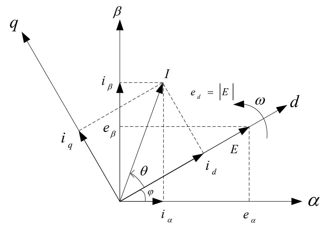
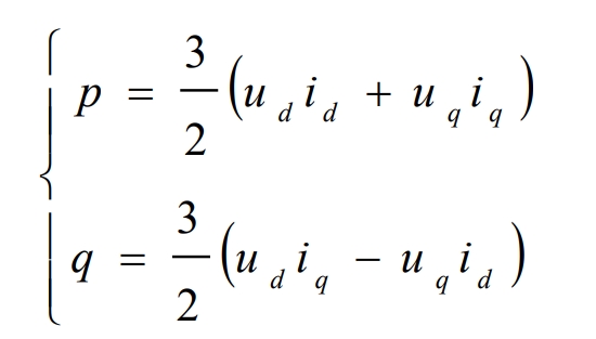
In the voltage vector oriented synchronous rotation (d, q) coordinates, ud=| U |, uq=0, active power is P, and reactive power is q.
Due to the grid voltage orientation, uq=0, the above equation can be simplified as:
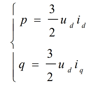
Assuming the voltage of the power grid is stable and ud is a constant value, it can be seen from the above equation that the values of active and reactive power are directly proportional to the components of the d and q axes. So, we can control the active and reactive power of the solar inverter by controlling the components id and iq on the d and q axes.
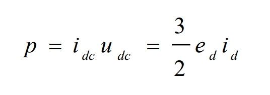
Due to the fact that in solar grid connected inverters, the output of the photovoltaic array is DC, there is only active power and no reactive power, i.e. instantaneous power p=udc idc. Ignoring losses, the formula can be used to obtain:
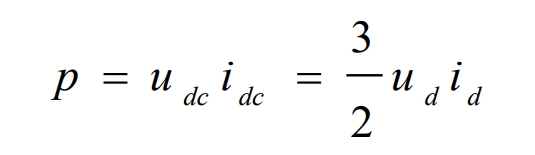
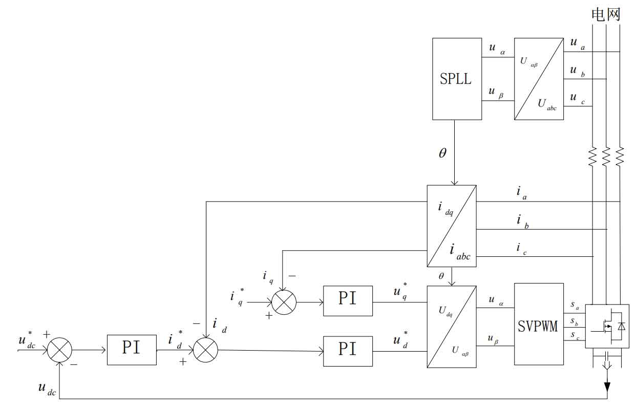
From the above equation, it can be seen that the DC voltage udc and active power p are directly proportional to the component id of the output current on the d-axis. Therefore, we can control the output DC voltage udc and output power by controlling the size of the id. The structure diagram of grid connected vector control for solar inverters based on voltage orientation is shown in Figure 2:
2. Current Control Theory Based on PI
PI control is currently one of the most commonly used methods for current control. Its control algorithm is simple and has high reliability. In the control system, we use a double closed-loop control, with the outer loop being the DC bus voltage loop and the inner loop being the ID and iQ current loops, which are active current and reactive current, respectively. The outer loop is mainly used to stabilize the DC voltage and prevent the impact of sudden changes on the grid connected current. PI control is to achieve zero difference adjustment of the DC current. We can control the voltage of the bus by controlling the ID, so the output after passing through the PI controller is the reference value i * d of the active current inner loop control, which controls the output current and active power of the solar inverter. We usually set the reference i * q of reactive current inner loop control to 0, because the solar inverter needs to operate in cos θ= In the state of 1, the solar inverter only transmits active power to the grid, i.e. i * q=0.
The current inner loop control is completed in the (d, q) coordinates by collecting the three-phase grid connected currents ia, ib, and ic, and then transforming them into the DC components id and iq in the (d, q) coordinates through coordinate transformation. Then, it is compared with the reference values i * d and i * q, and the PI regulator is used to achieve zero difference adjustment of id and iq. The variable adjusted by PI is then transformed back to obtain u α , U β, Then, the required driving signals Sa, Sb, Sc are obtained through SVPWM to achieve closed-loop control of the control system.
Assuming the three-phase sampling grid voltage is (ea, eb, ec), after coordinate transformation, (e) can be obtained α , E β) .
According to Kirchhoff’s law:
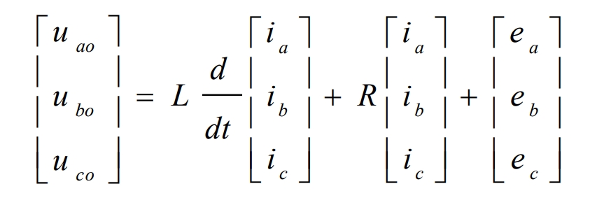
The mathematical model of the three-phase solar grid connected inverter obtained through coordinate transformation is:
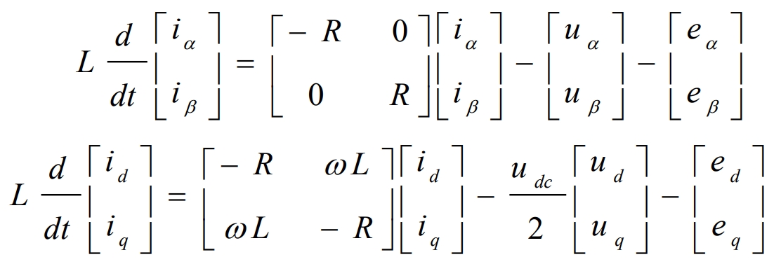
From the above equation, it can be seen that id and iq are coupled with each other, and a change in one phase will affect the change in the other phase, resulting in poor dynamic stability of the system. Therefore, we need to decouple and adopt a feedforward decoupling control strategy. The voltage command for controlling the current in the (d, q) coordinates obtained through PI adjustment is:
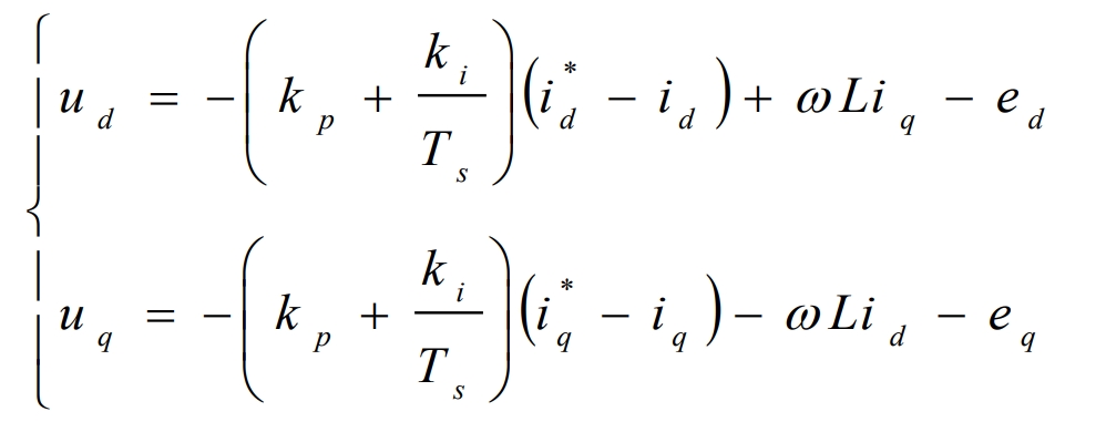
Among them, kp and ki represent the proportional coefficient and integral coefficient of the PI regulator, respectively. ω The angular frequency of the grid voltage. Ts is the sampling period.
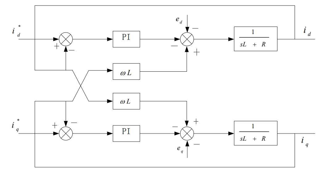
From the above equation, it can be seen that feedforward decoupling control achieves decoupling of the current loop. The control block diagram of the current loop is shown in Figure 3.
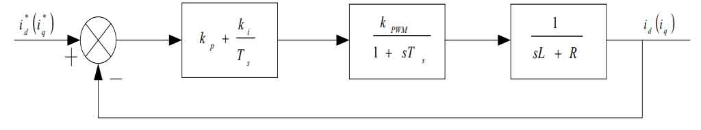
We set the disturbance as ed, and through the compensation of the PI regulator, we can obtain a simplified current loop control block diagram as shown in Figure 4. Among them, kpwm is the equivalent gain of three-phase bridge arm PWM.
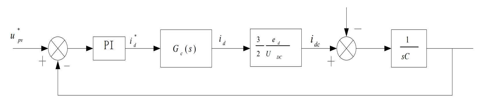
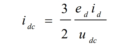
From the above analysis, it can be seen that the DC voltage of the busbar can be controlled by controlling the active current ID. From the structure diagram of the three-phase solar inverter, it can be seen that:
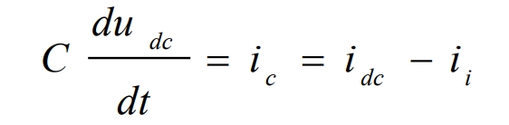
Therefore, to construct the DC voltage of the bus, we first need to know the relationship between the output ID of the inner loop and the DC input current idc, which is:
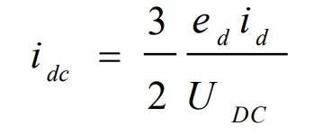
After simplification, it can be concluded that:
In a stable state, there is udc=UDC, so:
Thus, we can obtain the control block diagram of the voltage outer loop as shown in Figure 5. Among them, Gc (s) is the transfer function of the current inner loop.