The main function of three-phase solar grid connected inverters is to convert the direct current generated by the photovoltaic array into alternating current and then integrate it into the power grid. During the grid connection process, it is required that the voltage generated by the inverter be in the same phase, frequency, and amplitude as the grid voltage in order to be integrated into the grid. So the stability, safety, and design parameters of solar inverters are very important. To achieve DC to AC conversion in solar inverters, effective control methods are required. The most common and effective control method of space vector pulse width modulation will be adopted in this design.
1. Circuit topology of solar grid connected inverters
There are many types of circuit topologies for three-phase solar inverters, as we have already introduced earlier: isolated and non isolated, high-frequency and power frequency, single-stage and multi-stage [49], and so on. We can be divided into voltage type and current type based on the type of DC side power supply.
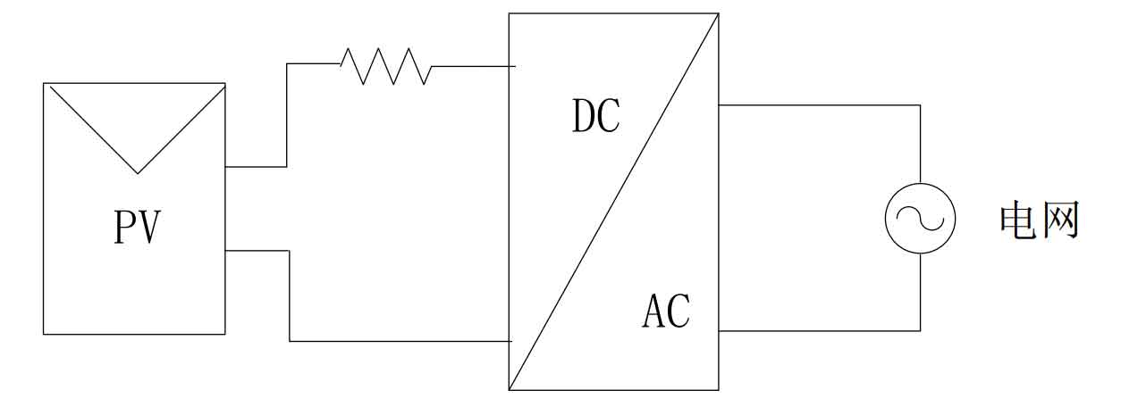
A current source inverter circuit is a series connected large inductor on the DC side, which increases the resistance on the DC power supply side and approximates it as a constant current source. This circuit topology structure will cause oscillation and current distortion problems with the AC side filter, which has a significant impact on the stability of the entire system and the control is also relatively complex. Therefore, current type topology structures are generally not used in three-phase solar grid connected inverters. The topology of the current source inverter circuit is shown in Figure 1.
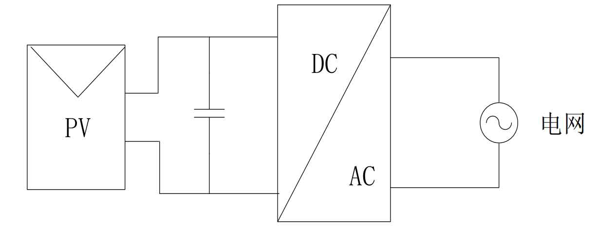
A voltage source inverter circuit is a large capacitor connected in parallel on the DC side, which reduces the resistance on the DC side and approximates it as a constant voltage source. This type of power supply has a simple structure and mature control technology, so voltage source inverter circuits are now widely used in three-phase inverter circuits. The topology structure of the voltage type inverter circuit is shown in Figure 2.
During the inverter process, there are also three-phase half bridge and three-phase full bridge inverter circuits, both of which have fewer electrical components and easier control methods to implement. We can add some resonant elements to the three-phase full bridge inverter circuit to make the inverter process more stable. The three-phase half bridge inverter circuit has a low utilization rate of voltage, only half of the DC voltage, and generally does not use a half bridge inverter circuit. So, the three-phase solar inverter we designed will use a voltage type three-phase full bridge inverter circuit.
2. Establishment of three-phase solar grid connected inverter model
We have already provided a basic introduction to the topology of the circuit. Now, we will focus on the LC type circuit topology and the establishment of mathematical models, and analyze its control strategies.
2.1 Coordinate transformation between Clark and Park
We commonly use three types of vector control coordinate systems: three-phase stationary coordinate systems (a, b, c), and two-phase stationary coordinate systems( α , β), Two phase rotating coordinate system (d, q). The Clark transform is the transformation of a three-phase stationary coordinate system to a two-phase stationary coordinate system, and the inverse transform is the inverse Clark transform. Usually, we align the axis of phase a in the three phases with the axis of phase a in the two phases α The phase axis coincides, usually with the current as the transformation object, as shown in Figure 3, where three-phase ia, ib, and ic are converted to two-phase i α, I β Coordinate transformation diagram.
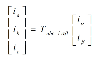
Clark coordinate transformation to:
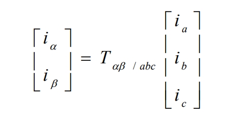
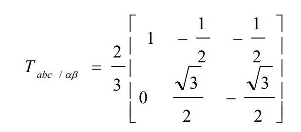
The Clark transformation matrix is Tabc/ αβ:
The inverse Clark transform is:
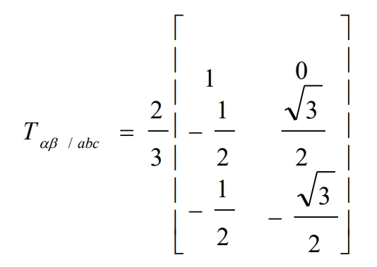
The inverse transformation matrix is T αβ/ Abc:
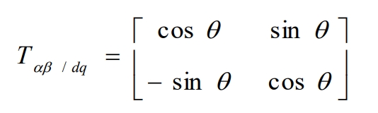
Park transformation is the transformation of a two-phase stationary coordinate system to a two-phase rotating coordinate system, where the two-phase rotating coordinate system (d, q) is at any fixed angular velocity ω Rotating. Usually, the transformation object is also based on the current, as shown in Figure 4 as the two-phase stationary coordinate i α , I β Schematic diagram of converting to two-phase rotating coordinates id and iq.
Park coordinate transformation to:
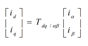
Park transformation matrix to T αβ/ Dq:
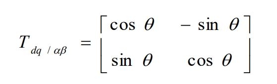
The inverse transformation of Park is:
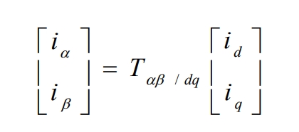
The inverse transformation matrix is T αβ/ Dq:
2.2 Mathematical model of LC type solar grid connected inverter
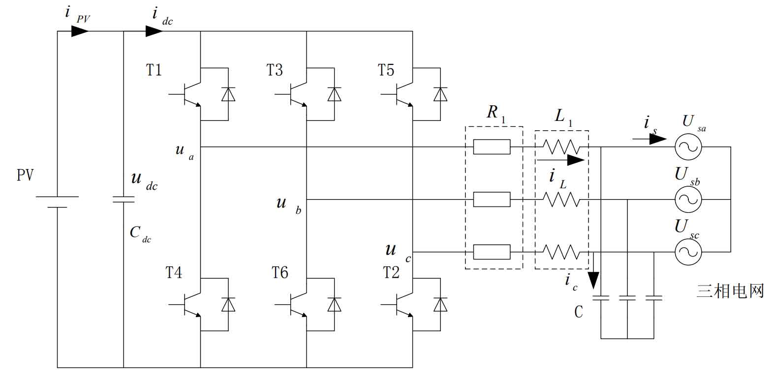
The three-phase solar grid connected inverter circuit of LC type filter is shown in Figure 5. The iPV outputs DC power to the photovoltaic array, Cdc is the DC side capacitor, idc is the input current of the solar inverter, R1 is the equivalent resistance of the filtering inductance, and the filtering inductance and capacitance are L1 and C, respectively. Is is the grid connected current on the grid side, and Usk (k=a, b, c) is the grid voltage. In order to obtain a better mathematical model, we made some assumptions: (1) The three-phase power grid is an ideal symmetrical sine voltage source. (2) The power switch used is an ideal component, regardless of its losses and voltage drops. (3) The frequency of power switches is much higher than that of the power grid.
Let the common node O of the three-phase power grid be at zero potential, and the function of the power switch is Sk (k=a, b, c).
According to Kirchhoff’s law:
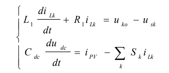
Among them, iLk is the current flowing through the inductor, and uko is the voltage of the inverter bridge arm to point O.
The grid connected current isk is:
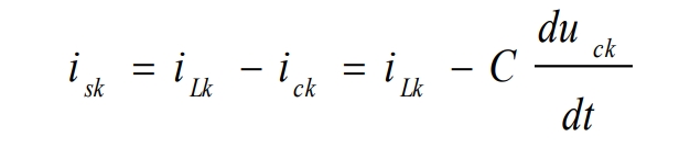
Among them, ick and uck represent the current flowing through the capacitor and the internal voltage of the capacitor, respectively.
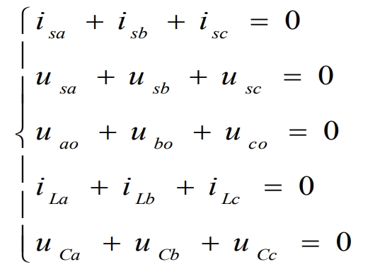
The equilibrium relationship that exists in an ideal circuit is:
According to Kirchhoff’s law:
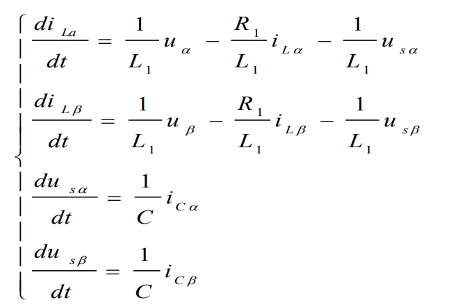
Among them, iL α And iL β Respectively, the inductance L( α, β ) In the coordinate system αβ The current vector on the axis. U α And u β The voltage on the AC side is respectively( α, β ) In the coordinate system α,β The voltage vector on the axis.
Combined with the formula, it can be concluded that( α, β ) The state equation in the coordinate system is:
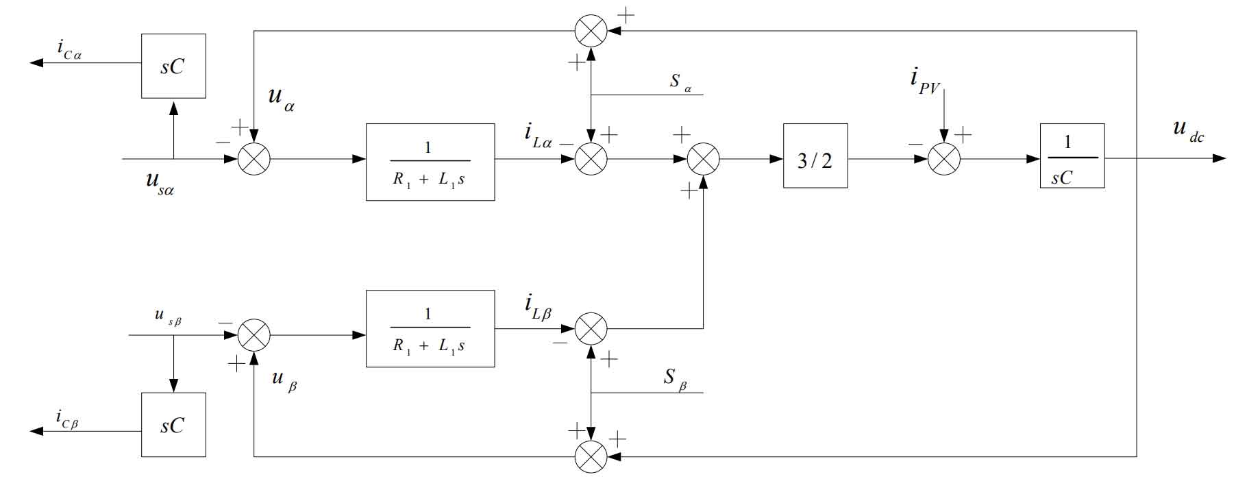
According to the formula, it can be concluded that the solar inverter is( α, β ) The mathematical model in the coordinate system is shown in Figure 6. In the( α, β ) The AC side voltage component in the coordinate system is:

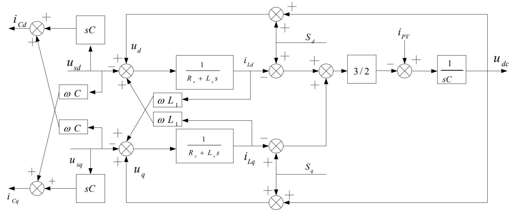
According to the above formula, after Clark and Park transformations, the mathematical model formula of the three-phase solar inverter in the (d, q) coordinate system can be obtained as follows:
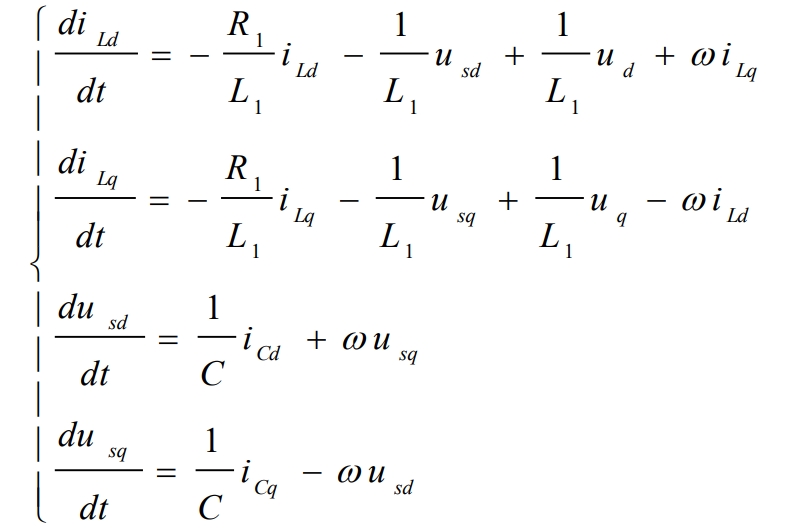
Among them, iLd and iLq are the current vectors of inductance L on the dq axis in the (d, q) coordinate system, respectively. Ud and uq are the voltage vectors of the AC side voltage on the dq axis in the (d, q) coordinate system, respectively.
The AC side voltage component in the (d, q) coordinate system is:
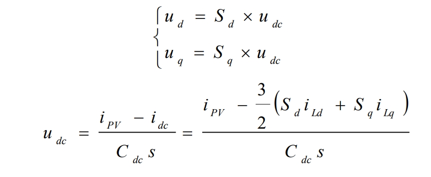
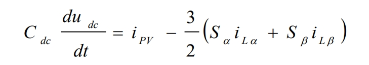
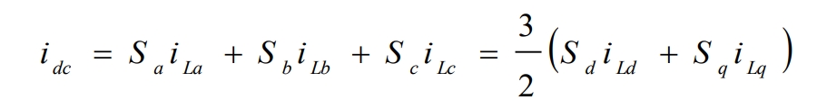
The expression for the input current idc of the solar inverter is:
The mathematical model of the solar inverter in the (d, q) coordinate system is obtained from the formula, as shown in Figure 7.