
In recent years, the introduction of energy storage in the power grid not only enables more effective utilization of power equipment, but also serves as a means to improve system operation stability and peak shaving frequency regulation.
With the development of energy storage technology, the scale of energy storage projects is gradually increasing. However, some problems have also been found in engineering practice, such as lack of experience in energy storage system regulation and operation maintenance, failure to achieve systematic global optimization in system regulation, high demand for infrastructure type energy storage, and long construction cycles. These issues pose new requirements for the application of energy storage systems.
Sinopec Sales Co., Ltd. South China Branch has built an energy storage power supply system at Huangpu Oil Pipeline Station to fully utilize the policy of “peak valley electricity prices” in Guangdong Province and promote the energy-saving application of advanced energy storage technology in the field of oil pipelines. Guangdong Zhicheng Champion Group Co., Ltd. undertook this project and completed the design, development, installation, and commissioning of a 1 MW · h energy storage power supply system. The structure and charging and discharging strategies were studied, and the optimal integration of the energy storage system was achieved. Through on-site debugging, it was verified that the energy storage system is reliable, economical, and environmentally friendly, and can meet practical work needs.
1. Scheme design of energy storage system
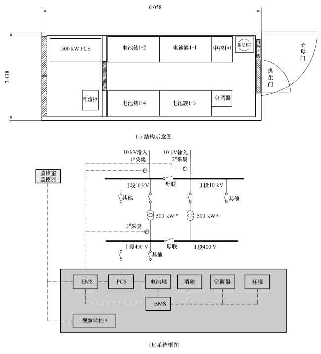
The distribution system of Huangpu Oil Pipeline Pump Station has two 10 kV inputs, and there is an 800 kV · A transformer connected to the 400 V busbar under each section of the busbar. The designed total power capacity of this energy storage system is 300 kW, with a total battery capacity of 995 328 kW · h (1 MW · h). It consists of a 300 kW energy storage bidirectional converter, four sets of battery clusters, one central control cabinet, one DC combiner cabinet, one industrial air conditioning system, one temperature control system, one BMS, and one fire protection system, all installed in a container and placed outdoors. The overall structure and schematic diagram of the energy storage system are shown in Figure 1.
The energy storage bidirectional converter (PCS), battery module, and battery management system (BMS) are the core components of the energy storage converter, which determine the performance of the entire system.
1.1 Energy Storage Bidirectional Converter (PCS)
This energy storage system is designed with one bidirectional energy storage inverter developed by Guangdong Zhicheng Champion Group Co., Ltd. inside the container. The topology structure of the energy storage bidirectional converter is shown in Figure 2.
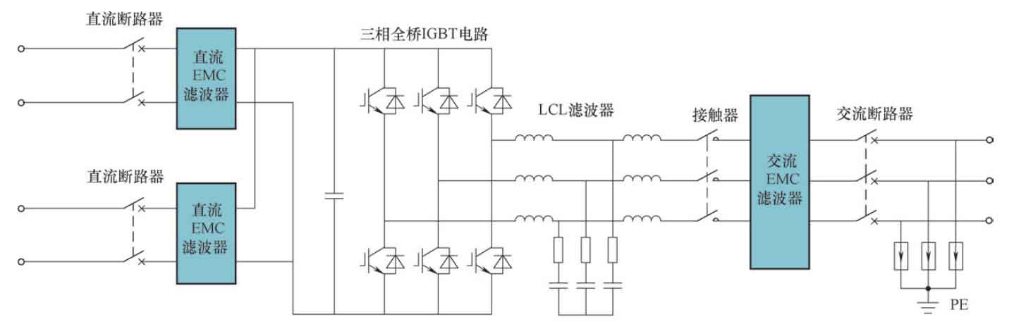
The energy storage bidirectional converter adopts DSP control and achieves bidirectional energy transfer between the DC battery of the battery storage system and the AC power grid through a three-phase full bridge IGBT circuit. Through control strategies, it realizes charge and discharge management of the battery system, tracking of grid side load power, and control of charge and discharge power of the battery storage system. It has the following functional characteristics.
1) This bidirectional converter can operate in both grid connected and off grid operating modes, and can seamlessly switch online between the two modes with short transition time, meeting the different needs of users in practical applications.
2) A series of hardware and software optimization measures have been adopted to reduce the power consumption of the device itself, and the conversion efficiency can reach 98% More than 5%, with excellent energy-saving characteristics, ensuring maximum energy utilization.
3) This bidirectional converter has various complete protection functions, such as overvoltage and undervoltage protection, overcurrent protection, short circuit protection, overload protection, anti islanding protection, and power flip protection, to ensure the safety of the system and power grid to the maximum extent possible.
4) Equipped with low voltage ride through function (LVRT). Has a certain ability to withstand voltage anomalies and will not detach in the event of abnormal voltage in the power grid, causing losses to the power supply.
5) This bidirectional converter adopts advanced software algorithms and excellent hardware topology structure, so the harmonic pollution generated by grid connected operation is minimal and will not have a significant impact on the power grid, meeting the design concept of green environmental protection.
6) In grid connected operation, reactive power can be injected into the grid according to the actual needs of the grid, remote instructions, or local settings, so that the grid connected power factor can be adjusted between -1 and 1, thereby achieving reactive power compensation for the grid.
7) Under off grid operation, it can generate high-quality AC power and meet the requirements of electricity load for power quality.
1.2 Battery module
This energy storage system uses lithium iron phosphate (LFP) batteries, which have the characteristics of high specific energy, long cycle life, low cost, high cost-effectiveness, high current charging and discharging, high temperature resistance, high energy density, no memory, and safety and no pollution. They have been widely used in energy storage systems. This plan uses a square shell hard pack with a rated capacity of 120 A · h and a rated voltage of 3 2 V lithium iron phosphate battery.
For the convenience of production installation and system management, the battery part of this energy storage system is divided into four battery clusters, as shown in Figure 3. Each battery cluster is composed of 18 battery modules in a combination of 1 parallel and 18 strings; Each battery module consists of 36 pieces of 120 A · h/3 A 2V lithium iron phosphate battery and one battery management unit (BMU) are used to control the battery cluster through one control box.
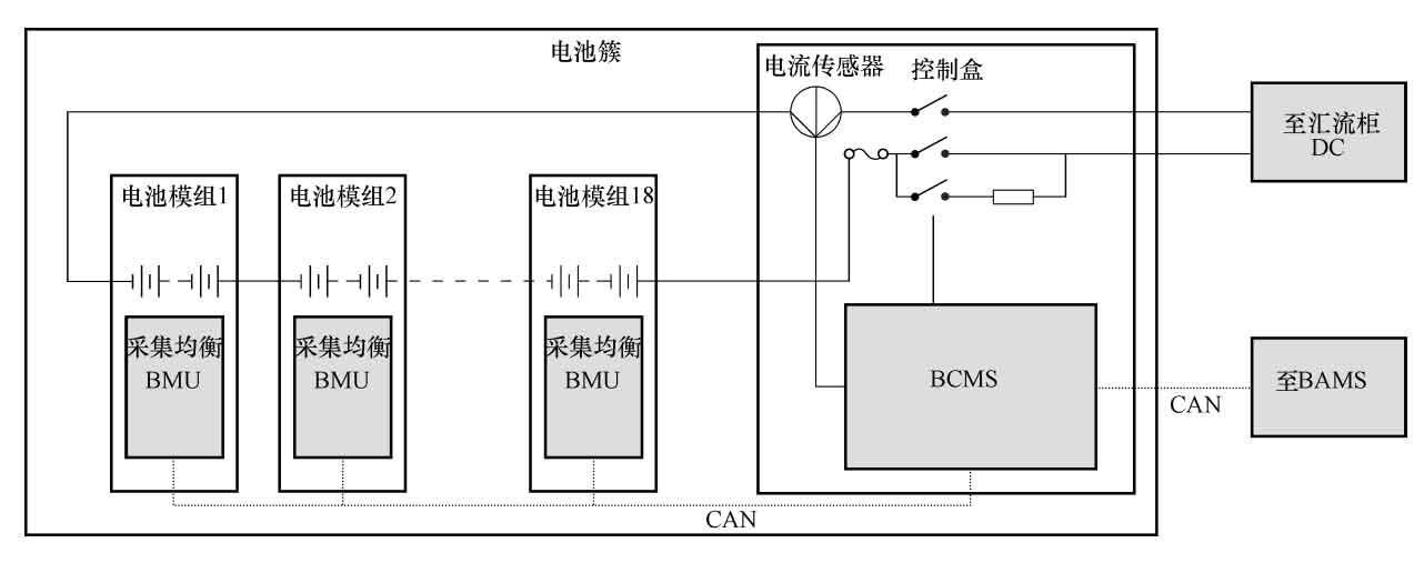
The battery cluster management unit (BCMS) is integrated into the control box, which collects battery module information downwards and provides information to the upper layer battery stack management system (BAMS). The battery cluster management unit collects information such as voltage, current, and temperature of the batteries in this cluster, and protects and controls the battery cluster.
1.3 Battery Management System (BMS)
BMS has a three-level management architecture: the first level is the Battery Module Management Unit (BMU); The second level is the Battery Cluster Management System (BCMS); The third level is the Battery Stack Management System (BAMS). The entire management system is mainly composed of components such as BMU, DMU, HMU, BCMS, and BAMS. BMU/DMU/HMU and BCMS use CAN communication, while BCMS and BAMS use both Ethernet and CAN communication, forming a dual loop redundant communication. The system architecture is shown in Figure 4. The first level BMS management unit (BMU) monitors the voltage, temperature, balancing current, and module total voltage of individual battery cells, and communicates in real-time with the second level BMS management unit through CAN protocol to control active balancing of battery cells.
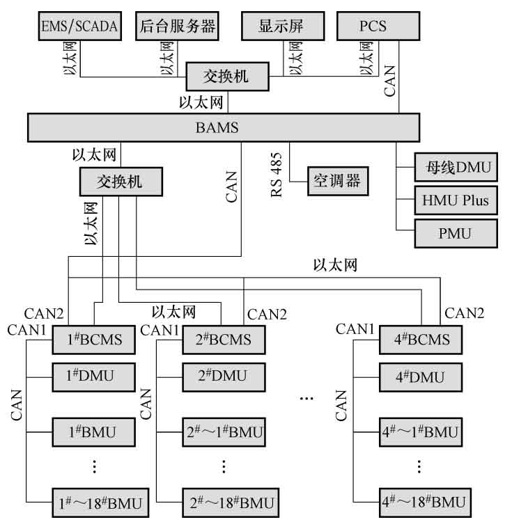
The secondary BMS management unit (BCMS) is capable of monitoring the total voltage, total current, and insulation resistance of the entire cluster of batteries, collecting external emergency stop signals, status information of switches in the high-voltage control box, and outputting fault and operating status.
The third level BMS management unit (BAMS) can collect information on the total voltage, total current, total power, and second level BMS of the system. It can accurately calculate the SOC, SOH, and cycle times of the battery system in real time, and can isolate data from the third and second level BMS management units to comprehensively manage the battery system.
1.4 DC combiner cabinet
The DC combiner cabinet is one of the main equipment of the box type energy storage system. Its function is to parallelize and converge various battery clusters, output them to PCS, and cooperate with the system monitoring device to monitor their output voltage, current, and insulation situation. With the help of the switch power supply, it can meet the power supply of key components in the system. Upload data or status information to the Battery Stack Management System (BAMS) through Ethernet communication, and receive commands from the management system to control the opening and closing of the DC busbar main switch.
2. Operation strategy of energy storage system
2.1 Energy Storage System EMS Energy Management System Description
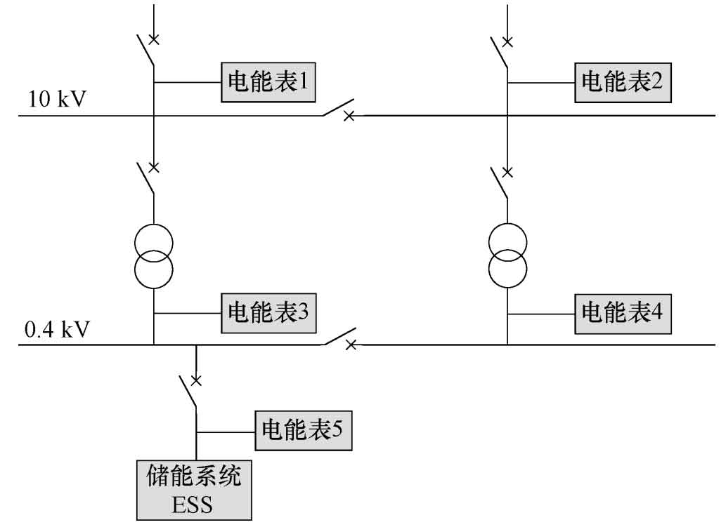
The power distribution system of Huangpu Oil Pipeline Pump Station consists of two 10 kV inputs and is automatically switched on as backup. There is one 800 kV · A transformer on each of the two busbars, which is converted to 400 V. This project will add 1 # to 4 # electricity meters on the factory side, and connect the energy storage system to 0 The topology of the 4 kV low-voltage bus section is shown in Figure 5.
This energy storage system operates in parallel with the mains power grid. Charge energy storage during low electricity prices at night, discharge to the outside during peak electricity prices during the day, and reduce the total electricity price through price differences.
The Energy Management System (EMS) serves as the control core of the energy storage system, managing charging and discharging based on set strategies, and optimizing and adjusting according to actual operating conditions. EMS can collect real-time and scheduled data on all monitored operating parameters and states; Collect common information of each group of batteries in the BMS, collect relevant parameters of the bidirectional inverter system, and collect various state variables of the energy storage system. Simultaneously collect data from electricity meters 1 # to 4 # within the station to prevent electricity from flowing into the grid and overloading transformers.
2.2 Control Strategy
1) According to the local peak, valley, and flat electricity prices of Huangpu Oil Pipeline Station, corresponding work strategies have been set up, as shown in Table 1.
| Working hours | Number | Electricity price | Time period | Work strategy | Valuation of charge and discharge capacity |
| Oil pump working hours | 1 | Valley | 00:00~08:00 | Charging | Charging 900 kW · h |
| Oil pump working hours | 2 | Levels | 08:00~09:00 | Standby | |
| Oil pump working hours | 3 | Peaks | 09:00~12:00 | Discharge | Discharge 900 kW · h |
| Oil pump working hours | 4 | Levels | 12:00~19:00 | Charging | Charging 900 kW · h |
| Oil pump working hours | 5 | Peaks | 19:00~22:00 | Discharge | Discharge 900 kW · h |
| Oil pump working hours | 6 | Levels | 22:00~00:00 | Standby | |
| Oil pump not working period | 7 | Valley | 00:00~08:00 | Charging | Charging 900 kW · h |
| Oil pump not working period | 8 | Levels | 08:00~09:00 | Standby | |
| Oil pump not working period | 9 | Peaks | 09:00~12:00 | Discharge | Discharge 450 kW · h |
| Oil pump not working period | 10 | Levels | 12:00~19:00 | Standby | |
| Oil pump not working period | 11 | Peaks | 19:00~22:00 | Discharge | Discharge 450 kW · h |
| Oil pump not working period | 12 | levels | 22:00~00:00 | Standby |
2) Ensure that the transformer is not overloaded during charging and that electrical energy does not flow into the grid during discharging. According to the actual load situation of Huangpu Oil Pipeline Station, when setting up charging, the collected power of either the 3 # and 4 # energy meters should not exceed 640 kW; When discharging, the power collected by either the 1 # energy meter or the 2 # energy meter shall not be less than 150 kW. This can ensure that the transformer is not overloaded during charging and that electrical energy does not flow into the grid during discharging. The 5 # energy meter is used to measure the charging amount of the energy storage system.
3) Operation strategy description. If the collected power of either the 3 # and 4 # energy meters reaches 640 kW during charging, the charging power of the energy storage system should be reduced to ensure that the 800 kV · A transformer does not experience overload; If the power collected by the 1 # and 2 # energy meters during discharge is less than 150 kW, the energy storage discharge power should be reduced to ensure that electricity does not flow into the grid.
2.3 Benefit estimation
The peak electricity price of Huangpu Oil Pipeline Station is 1 036 8 yuan/kW · h, with an average electricity price of 0 64 yuan/kW · h, with a valley price of 0 3348 yuan/kW · h. Set the discharge depth to 95%, i.e. the SOC range is 5%~100%, with a remaining 5% for each discharge. In this state, the lithium iron phosphate battery decays to 3000 times (90%), 5000 times (80%), and 7000 times (70%), with an actual usage capacity of 965 kW · h. Refer to the charging and discharging strategies shown in Table 1.
During the pump operation period, the daily revenue is calculated as: valley charging is 0 334 8 × 900 kW · h ≈ 301 32 yuan; The average charging is 0 sixty-four × 900 kW · h ≈ 576 yuan; The peak discharge is 1 036 8 × 1 800 kW · h ≈ 1 866 24 yuan; Daily income ≈ (1866 24-576-301 32) × 91% (efficiency) ≈ 900 yuan.
During the period when the pump is not working, the daily profit calculation is as follows: valley charging is 0 334 8 × 900 kW · h ≈ 301 32 yuan; The peak discharge is 1 036 8 × 900 kW · h ≈ 933 12 yuan; Daily return ≈ (933 12-301 32) × 90% (efficiency) ≈ 568 6 yuan.
Annual revenue estimation: Calculated based on an average of 63% of the pump operating hours at the Huangpu Oil Pipeline Pump Station (historical statistical data). The pump operates for 360 days × 63%=227 days, pump not working for 360 days × 37%=133 days, with an annual return of (900) × 227)+(568 six × 133)=279 924 yuan.
The annual number of charging and discharging cycles is 587. Based on this, it can be roughly assumed that the annual income will decrease by 90% after 5 years (approximately 2935 cycles), which is 279924 yuan × 90%=251 931 yuan; After 9 years, the annual income will decrease to 80% (approximately 5283 cycles), which is 279924 yuan × 80%=223 939 yuan; After 12 years, the annual income will decrease to 70% (approximately 7044 cycles), which is 279924 yuan × 70%=195946 yuan.
According to the estimated results above, the application of this energy storage power supply system in Huangpu Oil Pipeline Station can bring good economic benefits.
3. Debugging verification
The debugging results are shown in Table 2.
| Debugging project | Debugging instructions | Inspection results |
| System power on debugging | Power on the central control cabinet and DC combiner cabinet, debug the power supply of the system and the power on status of various components | Normal |
| Central control cabinet function debugging | Check emergency stop function, fire emergency stop and linkage function | Normal |
| DC cabinet function debugging | Check emergency stop function, fire emergency stop and linkage function | Normal |
| Communication debugging | Check communication between display screen and BAMS, communication between BAMS and CMS14 cluster, communication between BCMS and BMU, communication between BCMS and DMU, communication between BAMS and PCS | Normal |
| Cluster opening and closing debugging | Control operation, opening and closing function | Normal |
| PCS operation debugging | Debugging PCS to ensure normal operation, startup debugging, shutdown debugging, emergency stop debugging | Normal |
| Charging and discharging debugging | Check charging and discharging performance, BMS balance, alarm and protection status | Normal |
| Fire function debugging | Check single fire alarm and composite fire alarm functions | Normal |
| Battery inspection | Conduct one inspection test on all battery cells | Normal |
| Set power value working strategy | Check if the energy storage system operates according to the set charging and discharging time period and corresponding power values | Qualified |
| Anti transformer overload function | When checking the charging stage, if the collected power of either the 3 # energy meter or the 4 # energy meter at the 1 # and 2 # low-voltage inlet ports reaches 640 kW, the energy storage system will reduce the charging power to ensure that the 800 kV · A transformer is not overloaded | Qualified |
| Anti backflow function | When checking the discharge stage, if the collected power from Table 1 and Table 2 of the 1 # and 2 # high-voltage inlet ports is less than 150 kW, the energy storage will reduce the discharge power to ensure that electrical energy does not flow into the grid | Qualified |
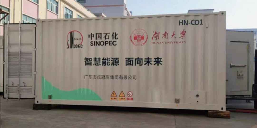
According to the inspection results and testing items described in the report, they meet the requirements of the inspection basis; The energy storage system has the conditions for grid connection and operation. The physical diagram of the energy storage system is shown in Figure 6.
4. Conclusion
The 1 MW · h energy storage power supply system studied uses standard modular design for battery modules and clusters, making it easy to install, transport, maintain, and expand the system, achieving optimal integration of the battery system. During the operation of the energy storage system, by optimizing control strategies, the transformer is not overloaded during charging and the electrical energy does not flow into the grid during discharging, which is reliable and environmentally friendly, and can bring economic benefits to the enterprise. The energy storage system has been running well since it was put into use.