
The energy storage power supply is usually composed of a large number of super capacitors, battery modules and other energy storage devices in series and parallel, and each module is composed of multiple energy storage units in series and parallel. Due to its internal resistance, energy storage devices generate a certain amount of heat during the charging and discharging process of energy storage systems. At the same time, most existing energy storage devices are sensitive to working temperature. If the temperature is too high, it will reduce the service life of energy storage devices, affect their performance, and in serious cases, trigger the system temperature protection function, affecting the normal use of vehicles.
At present, most of the ventilation and heat dissipation technology solutions for energy storage systems simply use vehicle air conditioning waste discharge to enter from both sides of the bottom of the cabinet, and cooperate with heat dissipation fans installed inside the cabinet to ventilate and cool the energy storage devices. However, this solution has the following shortcomings.
1) Most of the cooling air flows directly through the energy storage device directly above the air inlet to the fan, and the cooling air cannot flow evenly through the energy storage devices at various positions.
2) The fan is directly installed inside the cabinet, and the airflow to the fan at different positions in the cabinet depends only on the position relative to the fan, and the airflow cannot be adjusted.
3) There is no anti leakage structure at the air inlet, and there is a risk of liquid leakage from the energy storage device directly flowing into the air conditioning duct.
4) It is not possible to switch between natural air or forced air cooling mode for air conditioning exhaust based on the external environmental temperature.
Based on the engineering prototype project of intermittent power supply vehicle mounted energy storage system, our company has studied a new type of heat dissipation structure and method for energy storage power supply, which can achieve uniform cooling air flow through various energy storage devices inside the energy storage system. At the same time, it can switch between natural air or forced air cooling mode of air conditioning exhaust according to the operating environment temperature, improve heat dissipation efficiency, reduce heat dissipation energy consumption, and reduce temperature difference between various energy storage devices.
1. New heat dissipation methods for energy storage power supplies
The schematic diagram of the working principle of the new energy storage system’s heat dissipation method. The ventilation and heat dissipation system mainly consists of three parts: the inlet area, the device area, and the outlet area. Its specific working principle is as follows.
1) The cooling air of the air conditioner flows uniformly to different energy storage devices through leak proof liquid and air guiding devices.
2) Switch the natural cooling air cooling mode of the cooling system by adjusting the opening and closing of the natural air vents on both sides of the cabinet.
3) After passing through the energy storage device, all cooling airflow enters the air duct through the exhaust port on the independent air duct, and is finally discharged through the centrifugal fans at both ends of the air duct.
2. New Energy Storage Power Supply Heat Dissipation Structure
The specific structure and working principle of the ventilation and heat dissipation system of the new energy storage system are as follows.
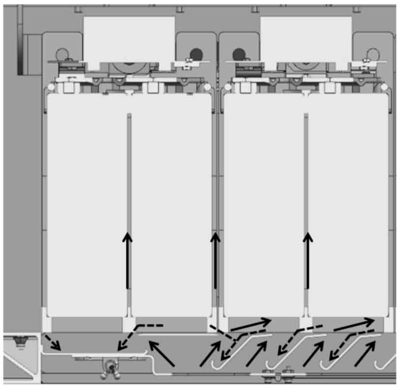
1) The new energy storage system enters the air from the bottom of the cabinet, as shown in Figure 1: The cooling air of the air conditioner flows to the energy storage devices at various positions of the cabinet through the air guide device, and dissipates heat through the ventilation gaps between the energy storage modules and inside, making the cooling air flow evenly to the energy storage devices at different positions as much as possible (the direction of the solid line arrow in the figure is the direction of the cooling air flow). At the same time, a leak proof device has been added at the air inlet. When a small amount of leakage occurs in the energy storage device, the electrolyte can flow into the leak proof tank through the corresponding guide structure (the direction indicated by the dashed arrow in the figure is the direction of the electrolyte leakage) to avoid direct leakage into the vehicle’s air conditioning duct.
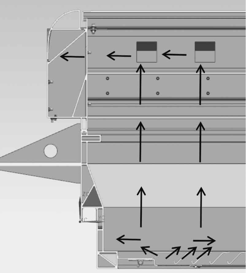
2) As shown in Figure 2, after passing through various energy storage devices, the cooling air flows through the air openings on both sides of the cabinet, and finally exits the cabinet through the fans on both sides of the air ducts. The black arrows in the figure indicate the direction of the cooling air flow. There may be differences in the cooling air volume at different positions of the air duct. By changing the size of the air outlets at different positions on the air duct and adjusting the incoming air volume, the cooling air can flow evenly through each air outlet on the air duct, achieving uniform heat dissipation of energy storage devices at different positions. In this cooling scheme, a new type of centrifugal fan is selected as the fan, which can be matched with different motors according to the cooling requirements of the energy storage system. Through this fan, the air volume can be controlled through real-time temperature adjustment and speed control of the cabinet, thereby achieving maximum heat dissipation and energy utilization.
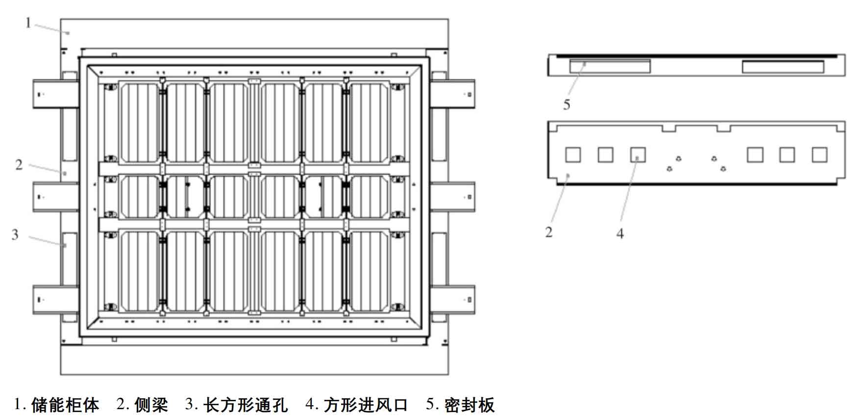
3) The natural air outlet can be manually adjusted to close according to different seasons, thereby changing the cooling air intake method of the energy storage system. The adjustable intake structure is shown in Figure 3: the side beams on both sides of the energy storage cabinet are square tubular profiles, with rectangular through holes at the bottom and square air intake holes on the side of the cabinet body. In the summer and autumn seasons (with an average external temperature greater than 20 ℃), the natural air inlet is closed through a sealing plate, and the energy storage system dissipates heat through air conditioning waste discharge; In the winter and spring seasons (with an average external temperature below 20 ℃), the sealing plate can be replaced with a filter. The natural wind from the outside can enter the cabinet through the side beam air inlet, providing cooling air for the energy storage system’s heat dissipation.
3. Conclusion
The simulation calculation and actual operation results of heat dissipation show that the new heat dissipation method for energy storage power supplies has good effects on improving the uniformity of heat dissipation between internal components, improving heat dissipation efficiency, and reducing energy consumption. It has certain reference significance for the research and application of heat dissipation methods for energy storage power supplies in the future.